Calibration Method of Laser Scanning Accuracy Controlled by Galvanometer

A technology of laser scanning and correction method, which is applied in the direction of additive manufacturing, process efficiency improvement, additive processing, etc. It can solve the problems of poor precision and long time-consuming laser scanning precision correction, and achieve the goal of reducing the difficulty of correction and eliminating the need for correction steps Effect

Active Publication Date: 2018-09-07
HARBIN FORWEDO MULTI DIMENSIONAL INTELLIGENT EQUIP CO LTD
View PDF8 Cites 0 Cited by
  • Summary
  • Abstract
  • Description
  • Claims
  • Application Information

AI Technical Summary

Problems solved by technology

[0005] Aiming at the defects existing in the prior art, the present invention provides a galvanometer-controlled laser scanning precision correction method, which can effectively solve the time-consuming and poor accuracy of laser scanning precision correction due to human interference factors in traditional laser scanning correction. question

Method used


Image

  • Calibration Method of Laser Scanning Accuracy Controlled by Galvanometer
  • Calibration Method of Laser Scanning Accuracy Controlled by Galvanometer
  • Calibration Method of Laser Scanning Accuracy Controlled by Galvanometer

Examples


Embodiment Construction

[0034] The present invention is described in detail below in conjunction with accompanying drawing:

[0035] The invention provides a laser scanning accuracy correction method controlled by a vibrating mirror. By introducing a similar printing technology, the equidistantness and collinearity of the feature points are guaranteed in advance, and then the laser spot is adjusted to align with the feature points, so that in a short time The position accuracy of the laser scanning plane can be calibrated within a few minutes, saving time and effort, and the accuracy is greatly improved.

[0036] Specifically, such as Figure 4 As shown, the galvanometer control laser scanning accuracy correction method provided by the present invention includes the following steps:

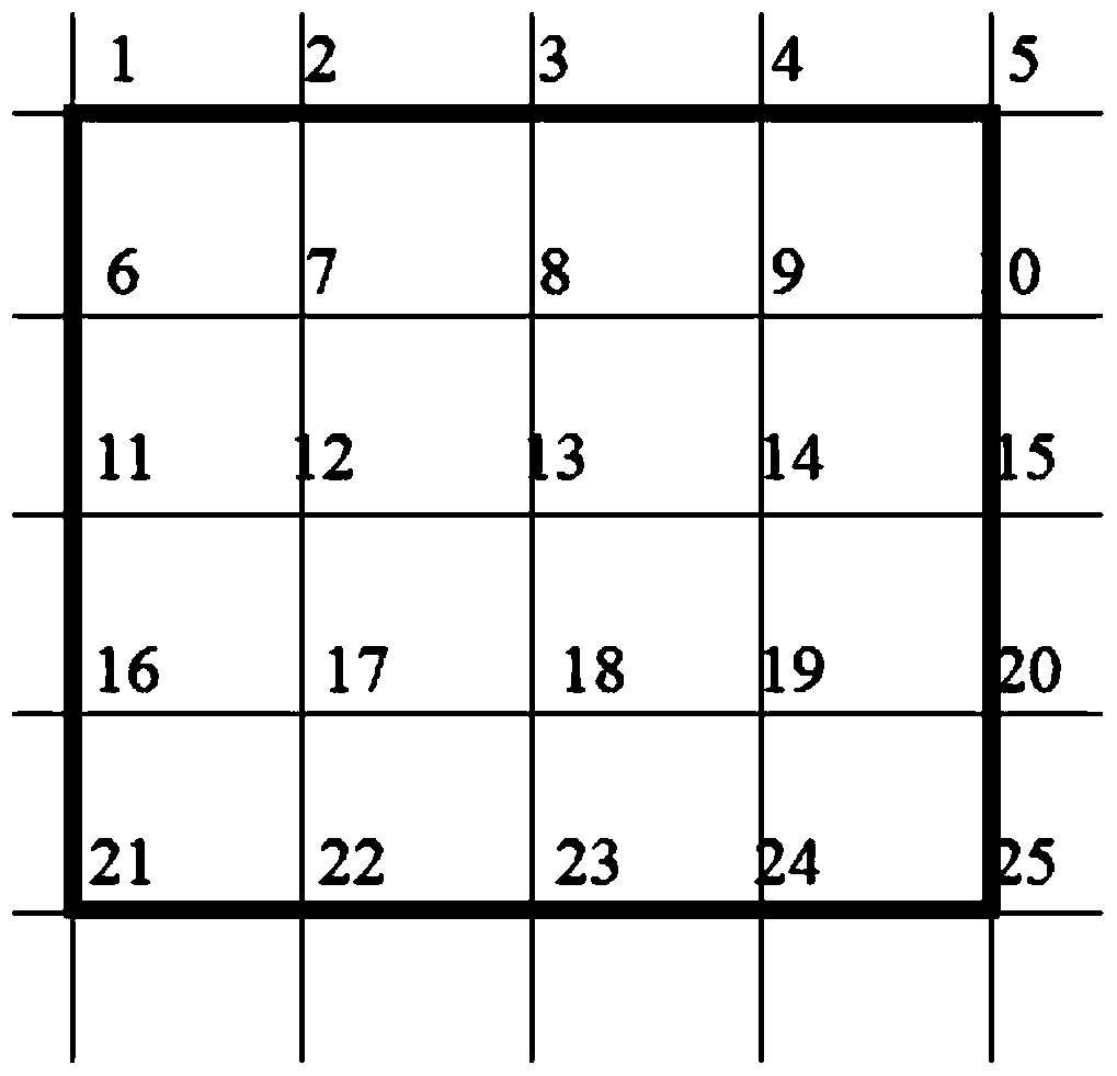
[0037] Step 1, when it is necessary to correct the scanning accuracy of the laser for a specific shape area, draw a square outside the specific shape area so that the specific shape area completely surrounds the inner ...


PUM


Abstract

The invention provides a laser scanning accuracy correction method controlled by a vibrating mirror. The steps are: using drawing software to draw 5 horizontal lines and 5 vertical lines in equal proportions to obtain 25 feature point area graphics; The proportion of the cardboard is printed on the cardboard; the standard cardboard is placed on the laser scanning focal plane, and the feature points are corrected sequentially through the correction software, so that the laser beam projected on the cardboard through the galvanometer is consistent with the laser spot on the standard cardboard. The corresponding feature points coincide to complete the laser scanning correction. The advantage is: compared with the traditional correction method, the present invention adopts the method of directly printing out the cardboard with standard 25 feature points, and then only needs to directly observe whether the laser spot projected on the cardboard coincides with the corresponding feature points; instead of first Through the method of laser output marking, and then measuring and point-by-point adjustment; the invention saves cumbersome correction steps and reduces the difficulty of correction.

Description

technical field [0001] The invention belongs to the technical field of metal powder laser melting and additive manufacturing, and in particular relates to a laser scanning precision correction method controlled by a vibrating mirror. Background technique [0002] With the continuous innovation and development of science and technology, the market competition has become increasingly fierce, and the continuous diversification of social needs has shortened the product update cycle. For some metals with special properties and complex structures in the fields of aerospace, ships and weaponry Parts, such as aero-engine turbine discs, are usually made of difficult-to-machine materials. Traditional methods of processing and manufacturing often have a long processing cycle, and the utilization rate of materials is extremely low, especially for parts with high complexity, even the manufacturing cannot be completed, and it is difficult to meet the market demand of the society. [0003...

Claims


Application Information

Patent Timeline
Patent Type & Authority Patents(China)
IPC IPC(8): B22F3/105
CPCB22F10/00B22F10/80B22F12/49B22F12/90B22F10/31B22F10/36Y02P10/25
Inventor 张佳刘邦涛张爱平潘志军全清友
Owner HARBIN FORWEDO MULTI DIMENSIONAL INTELLIGENT EQUIP CO LTD
Why Eureka
Try Eureka