Numerical control machining equipment for producing motor shell for new energy vehicle

A technology for motor housings and new energy vehicles, applied in metal processing equipment, metal processing mechanical parts, manufacturing tools, etc., can solve problems such as reducing the production efficiency of motor housings, causing quality problems, and fixing motor housings. To achieve the effect of convenient and efficient direction adjustment, easy assembly, and prevention of reverse rotation

Active Publication Date: 2022-03-29
深圳市金卓五金塑胶制品有限公司
View PDF10 Cites 4 Cited by
  • Summary
  • Abstract
  • Description
  • Claims
  • Application Information

AI Technical Summary

Problems solved by technology

[0003] Traditional new energy vehicle motor shell production CNC machining equipment, first of all need to place the motor shell on a specific storage table, and then process it, because The motor housing needs to be processed in multiple places on the side, so the axial position of the motor housing needs to be continuously adjusted to meet the production needs, and the existing storage table cannot ensure that the motor housing is well fixed and at the same time , the axial position of the motor housing can be adjusted in time according to the needs, and recalibration is required after the direction is adjusted. Due to the increase in the number of times, the possibility of negligence is also greatly increased, and it may even lead to occurrence of Quality problems, reducing the production efficiency of the motor casing

Method used


Image

  • Numerical control machining equipment for producing motor shell for new energy vehicle
  • Numerical control machining equipment for producing motor shell for new energy vehicle
  • Numerical control machining equipment for producing motor shell for new energy vehicle

Examples


Embodiment Construction

[0030] The following will clearly and completely describe the technical solutions in the embodiments of the present invention with reference to the accompanying drawings in the embodiments of the present invention. Obviously, the described embodiments are only some, not all, embodiments of the present invention. Based on the embodiments of the present invention, all other embodiments obtained by persons of ordinary skill in the art without making creative efforts belong to the protection scope of the present invention.

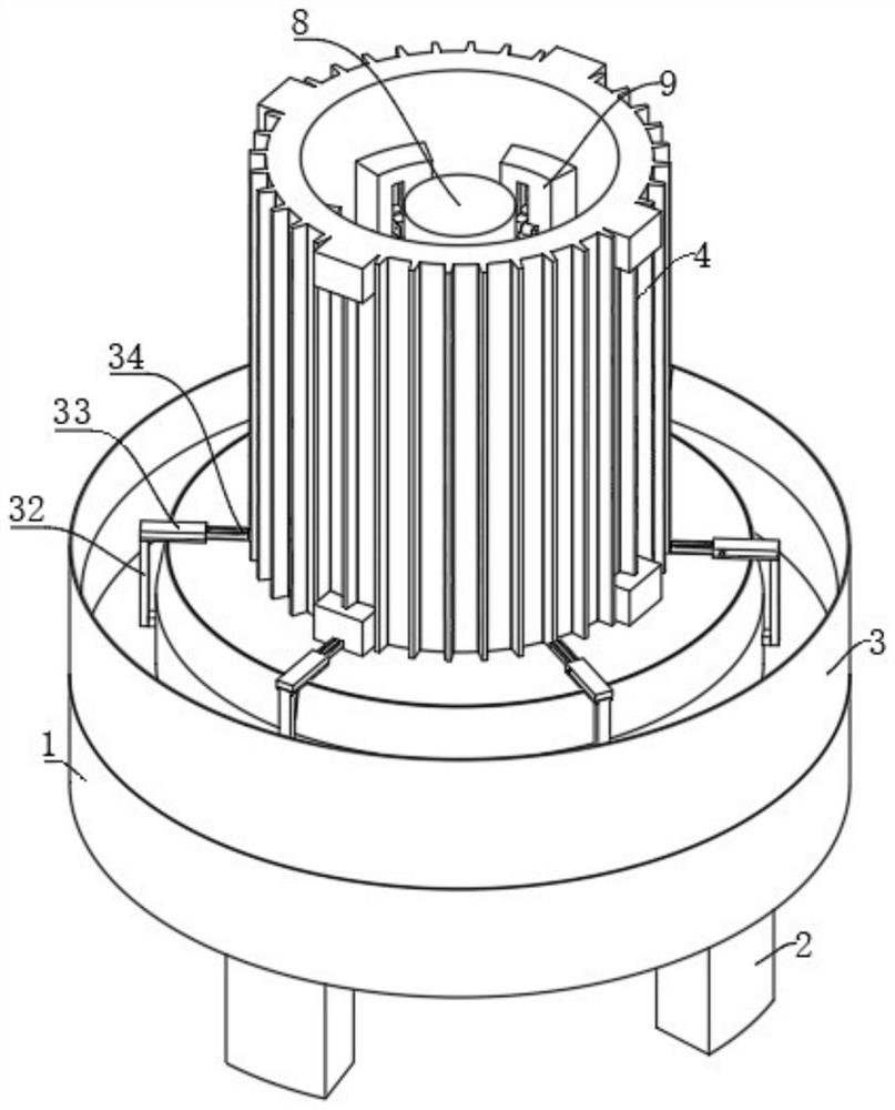
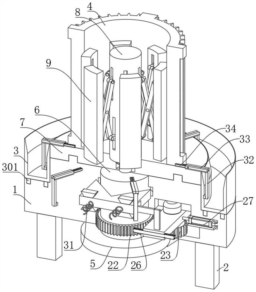
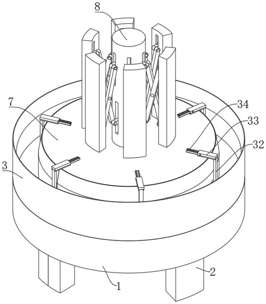
[0031] see Figure 1 to Figure 10 , the present invention provides a technical scheme of numerical control processing equipment for the production of motor housings for new energy vehicles: including a processing platform 1 and a motor housing assembly assembly arranged on the processing platform 1, the motor housing assembly assembly is from top to bottom It includes a column 8, an upper limit platform 7, a center column 6 and a lower limit plate 5 in sequenc...


PUM


Abstract

The new energy vehicle motor shell production numerical control machining equipment comprises a machining platform and a motor shell assembling assembly arranged on the machining platform, the motor shell assembling assembly sequentially comprises a stand column, an upper limiting table, a center column and a lower limiting disc from top to bottom, and the upper limiting table is rotationally installed on the upper end face of the machining platform; the center column is driven by a first driving device to rotate, a center column axial limiting mechanism is arranged in the machining platform, a motor shell is placed at the upper end of the upper limiting table, a motor shell clamping mechanism is arranged on the stand column and mainly comprises a plurality of inner pressing strips, each inner pressing strip is movably connected with a set of X-shaped hinge pieces, and the inner pressing strips are movably connected with the motor shell clamping mechanism. And the plurality of X-shaped hinging pieces are driven by a second driving device to do telescopic motion. While the motor shell is stably clamped, the position of the motor shell can be correspondingly adjusted according to requirements, and the production efficiency of the motor shell is effectively improved.

Description

technical field [0001] The invention relates to the technical field of motor generators, in particular to a numerically controlled processing equipment for producing motor casings for new energy vehicles. Background technique [0002] The motor generator used in the existing new energy vehicles is mainly used to drive or assist the operation of the vehicle. The motor generator refers to an electromagnetic device that realizes the conversion or transmission of electric energy according to the law of electromagnetic induction. The motor is represented by the letter M in the circuit. , its main function is to generate driving torque, as a power source for electrical appliances or various machinery, the generator is represented by the letter G in the circuit, its main function is to convert mechanical energy into electrical energy, and the motor shell is the motor The casing for protecting the internal structure of the generator needs to go through multiple steps in the processi...

Claims


Application Information

Patent Timeline
Patent Type & Authority Applications(China)
IPC IPC(8): B23Q3/08B23Q11/00
CPCB23Q3/08B23Q11/0067B23Q11/0042B23Q2703/04
Inventor 刘标
Owner 深圳市金卓五金塑胶制品有限公司
Why Eureka
Try Eureka