Excavator boom flow regeneration and potential energy recovery energy-saving device

An energy-saving device and potential energy recovery technology, which is applied to earth movers/excavators, construction, etc., can solve problems such as waste of energy, complex structure, and low recovery efficiency, so as to avoid throttling loss, avoid system heating, and improve efficiency Effect

Active Publication Date: 2022-03-29
江苏图南液控科技有限公司
View PDF6 Cites 0 Cited by
  • Summary
  • Abstract
  • Description
  • Claims
  • Application Information

AI Technical Summary

Problems solved by technology

[0003] Some of the existing excavator hydraulic energy recovery devices adopt the method of power generation-energy storage-electric release, the device is complicated, there are many energy conversion links, and the recovery efficiency is low; most of the hydraulic recovery adopts the scheme of quantitative motor and variable pump tow, The structure is complex, the volume is large, the weight is heavy, the cost is high, and a new type of hydraulic transformer is used. Due to its own structure and principle, the flow rate also changes when the transformation ratio is changed, which affects the control performance of the excavator and Causes unstable motion of the actuator
[0004] Since the boom needs to be lifted and lowered frequently during the working process of the excavator, when the boom is falling, the potential energy of the boom is converted into heat energy through the throttling effect of the valve port in a system without a potential energy recovery device, which not only wastes energy, but also Make the quality of hydraulic oil worse
[0005] When the hydraulic excavator is working, the potential energy generated when the large-mass boom is lifted is converted into heat energy and dissipated through the throttling of the hydraulic valve when it is lowered. High, in order to prevent the oil from being unusable due to the decrease in viscosity due to overheating, an additional cooling device with a larger specification is required to cool down, which increases the installed cost and working power of the hydraulic excavator

Method used


Image

  • Excavator boom flow regeneration and potential energy recovery energy-saving device
  • Excavator boom flow regeneration and potential energy recovery energy-saving device

Examples


Embodiment Construction

[0024] The specific implementation manner of the present invention will be further described below in conjunction with the accompanying drawings. Wherein the same components are denoted by the same reference numerals.

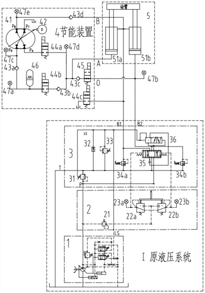
[0025] The invention provides an energy-saving device for excavator boom flow regeneration and potential energy recovery based on a four-port hydraulic transformer, such as figure 1 As shown, it includes a load-sensing hydraulic pump 1 , a pilot control valve block 2 , a main control valve block 3 , an energy-saving device 4 , and a boom cylinder 5 . Among them, the load sensitive hydraulic pump 1, the pilot control valve block 2, the main control valve block 3 and the boom oil cylinder 5 are the original hydraulic system of the existing excavator. The composition and function of the mature valve-controlled hydraulic system of the existing excavator have not been changed.

[0026] Since the present invention only considers the flow regeneration and potential ...


PUM


Abstract

The invention discloses an excavator movable arm flow regeneration and potential energy recovery energy-saving device which comprises a load-sensitive hydraulic pump, a pilot control valve block, a main control valve block and a movable arm oil cylinder and further comprises three working oil ports formed in the outer portion of the energy-saving device. The energy-saving device internally comprises a four-port hydraulic transformer, a servo motor, a one-way valve, a valve plate, a normally-closed electromagnetic valve, a normally-open electromagnetic valve, an energy accumulator and a pressure sensor. The excavator movable arm flow regeneration and potential energy recovery energy-saving device based on the four-port hydraulic transformer has the advantages that according to pressure values measured by all the pressure sensors, the controller controls the corresponding electromagnetic valves to act, the energy-saving device is switched into a hydraulic loop, the servo motor is adjusted through the controller, and the energy-saving effect of the excavator movable arm flow regeneration and potential energy recovery energy-saving device is achieved. A control angle of a valve plate of the four-port hydraulic transformer is changed, so that the transformation ratio of the four-port hydraulic transformer is changed, and hydraulic energy converted from gravitational potential energy in the descending process of the movable arm of the excavator is stored in the energy accumulator.

Description

technical field [0001] The invention relates to the technical field of hydraulic transmission and control, in particular to an energy-saving device for flow regeneration and potential energy recovery of an excavator arm. Background technique [0002] Energy recovery research is one of the hot issues in the field of construction machinery such as hydraulic excavators. In typical working conditions of hydraulic excavators, the recoverable energy of the boom accounts for more than 40% of the total recoverable energy of the whole machine, which is the key to energy recovery. preferred object. [0003] Some of the existing excavator hydraulic energy recovery devices adopt the method of power generation-energy storage-electric release, the device is complicated, there are many energy conversion links, and the recovery efficiency is low; most of the hydraulic recovery adopts the scheme of quantitative motor and variable pump tow, The structure is complex, the volume is large, the ...

Claims


Application Information

Patent Timeline
Patent Type & Authority Applications(China)
IPC IPC(8): E02F9/22
CPCE02F9/22E02F9/2267
Inventor 乐天刘强陈曦邹宇龄乐鹏陈伟孟波
Owner 江苏图南液控科技有限公司
Why Eureka
Try Eureka