
Imaging method based on linear array infrared detector

An infrared detector and imaging method technology, applied in the field of image processing, can solve problems such as poor reliability of scanning galvanometers and large peak currents, and achieve the effects of improving reliability, reducing peak currents, and improving image distortion

Active Publication Date: 2022-03-29
湖北久之洋信息科技有限公司
View PDF5 Cites 0 Cited by
  • Summary
  • Abstract
  • Description
  • Claims
  • Application Information

AI Technical Summary

Problems solved by technology

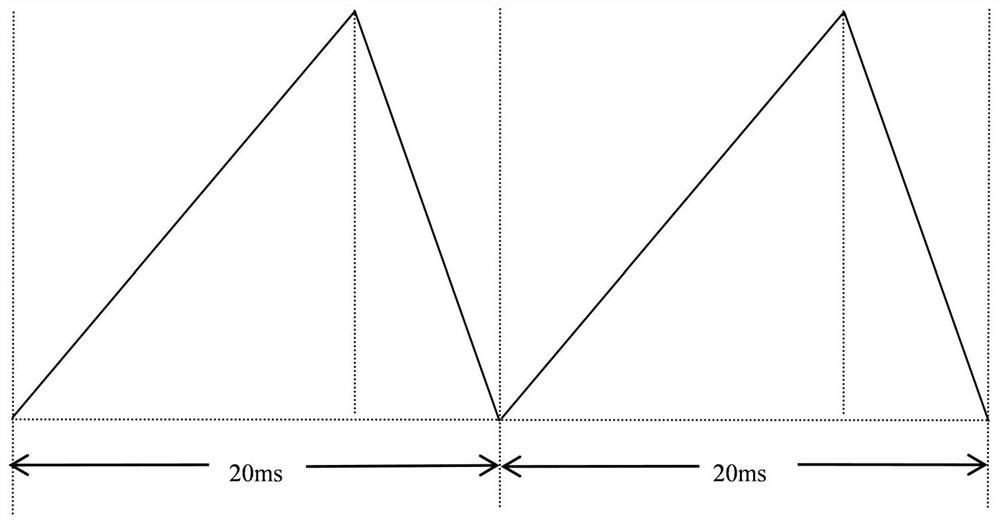
The problem caused by this is that the scanning curve forms an acute angle during the forward scanning and blanking transition time, and the scanning galvanometer needs to quickly realize the reentry movement, resulting in poor reliability of the scanning galvanometer and high peak current

Method used


Image

  • Imaging method based on linear array infrared detector
  • Imaging method based on linear array infrared detector
  • Imaging method based on linear array infrared detector

Examples


Embodiment Construction

[0034] In order to make the purpose, technical solutions and advantages of the embodiments of the present disclosure clearer, the technical solutions of the embodiments of the present disclosure will be clearly and completely described below in conjunction with the accompanying drawings of the embodiments of the present disclosure. Apparently, the described embodiments are some of the embodiments of the present disclosure, not all of them. Based on the described embodiments of the present disclosure, all other embodiments obtained by persons of ordinary skill in the art without creative effort fall within the protection scope of the present disclosure.

[0035] This embodiment adopts domestic long-wave infrared 288×4HgCdTe focal plane detector, PAL system video signal output, digital signal frame frequency 50Hz, resolution 768×288.

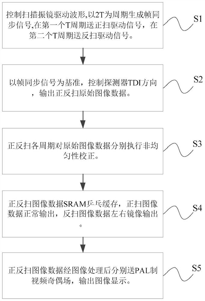
[0036] see figure 2 , image 3 , Figure 4 , an imaging method based on a linear infrared detector, the method comprises the following steps:...


PUM


Abstract

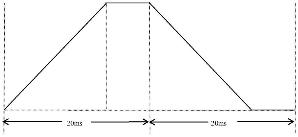
The invention discloses an imaging method based on a linear array infrared detector, and the method comprises the following steps: S1, taking 2T as the scanning period of a scanning galvanometer when the frame period of the detector is T, and dividing the scanning period into a forward scanning period T1 and a reverse scanning period T2 which are equal in period length; s2, enabling the time delay integral direction of the detector to be consistent with the motion direction of the scanning galvanometer; s3, performing non-uniformity correction on each period of forward scanning and reverse scanning; s4, performing ping-pong caching on the corrected data; and S5, performing image processing on the forward and reverse scanning data, and outputting the processed data. According to the method, the motion mode of the scanning galvanometer is changed, so that the scanning motion curve has no acute angle, the reliability of the galvanometer module is improved, the peak current is effectively reduced, and the image distortion is improved.

Description

technical field [0001] The invention relates to the technical field of image processing, in particular to an imaging method based on a linear infrared detector. Background technique [0002] At present, cooling infrared imaging systems can be divided into two types according to the imaging methods: linear infrared optical mechanical scanning imaging and infrared staring focal plane array imaging. The process of linear infrared optical mechanical scanning imaging is to scan the scene one-dimensionally in a row as a unit, and the horizontal one-dimensional scanning is realized by driving the optical lens through a mechanical turntable. Infrared detectors made of linear infrared optical mechanical scanning imaging methods have been developed and put into practical use. [0003] see figure 1 , the traditional scan control curve moves with the frame period as the cycle, which is divided into positive scan area and blanking area. The two-dimensional imaging of the detector is c...

Claims


Application Information

Patent Timeline
Patent Type & Authority Applications(China)
IPC IPC(8): G01J5/48
CPCG01J5/00G01J2005/0077Y02P70/50
Inventor 胡鹏博刘兴超叶小风阮建斌邓小毛栾金洁
Owner 湖北久之洋信息科技有限公司
Learn More