Flywheel energy storage system with electromagnetic coupler
An electromagnetic coupling, flywheel energy storage technology, applied in the field of flywheel energy storage system, can solve the problem of increasing the unbalanced power impact of the system
- Summary
- Abstract
- Description
- Claims
- Application Information
AI Technical Summary
Problems solved by technology
Method used
Image
Examples
Embodiment 1
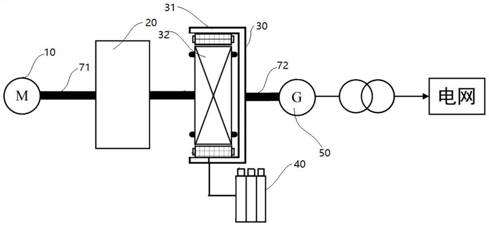
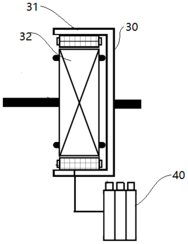
[0077] Such as figure 1 and figure 2 As shown, the flywheel energy storage system 1 of the present embodiment includes an electric motor 10, a flywheel 20, an electromagnetic coupler 30, a frequency converter 40, a generator 50, a first transfer shaft 71, a second drive shaft 72. The electromagnetic coupler 30 includes an inner rotor 32 and the outer rotor 31, and the inner rotor 32 is an input end of the electromagnetic coupler 30, and the outer rotor 31 is connected to the input end of the generator 50.
[0078] The motor 10 is located on one side of the flywheel rotor 20, and the first transport shaft 71 passes through the flywheel rotor 20 and transmits the flywheel rotor 20, and the transmission shaft 30 is transmitted to the output end of the motor 10. Connect, the other end of the first drive shaft 71 is connected to the inner rotor 32. One end of the second drive shaft 72 is connected to the outer rotor 31, and the other end of the second drive shaft 72 is connected to the...
Embodiment 2
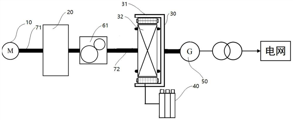
[0085] Below image 3 Taking the flywheel energy storage system 1 of the present embodiment, the flywheel energy storage system 1 of the present embodiment includes an electric motor 10, a flywheel 20, an electromagnetic coupler 30, a frequency converter 40, a generator 50, and a speed ratio shifting device 61. The first transfer shaft 71, the second drive shaft 72, and the third transmitting shaft 73. The flywheel rotor 20, the motor 10, and the electromagnetic coupler 30 are similar to the embodiment, and the difference portions are not described herein.
[0086] Such as image 3 As shown, the first transport shaft 31 passes through the flywheel rotor 20 and transmits one end of the flywheel shaft 31 and the output end of the motor 10, and the other end of the first drive shaft 3 and the fixed speed ratio shift speed. The input end of the device 61 is driven. One end of the second drive shaft 32 is connected to the output terminal of the fixed speed ratio shifting device 61, and t...
Embodiment 3
[0095] Below Figure 4 Taking the flywheel energy storage system 1 of the present embodiment, the flywheel energy storage system 1 of the present embodiment includes an electric motor 10, a flywheel 20, an electromagnetic coupler 30, a frequency converter 40, a generator 50, a speed ratio adjustable device 62, The first transfer shaft 71, the second drive shaft 72, and the third transmitting shaft 73. The flywheel rotor 20, the motor 10, and the electromagnetic coupler 30 are similar to the embodiment, and the difference portions are not described herein.
[0096] Such as Figure 4 As shown, the first transport shaft 31 passes through the flywheel rotor 20 and transmits from the flywheel rotor 20, and one end of the first drive shaft 31 is connected to the output of the motor 10, and the other end of the first drive shaft 31 is adjustable. The input end of the device 62 is connected. One end of the second drive shaft 32 is connected to the output terminal of the shift ratio adjustme...
PUM
 Abstract
Description
Claims
Application Information
 - R&D
- Intellectual Property
- Life Sciences
- Materials
- Tech Scout
- Unparalleled Data Quality
- Higher Quality Content
- 60% Fewer Hallucinations
Browse by: Latest US Patents, China's latest patents, Technical Efficacy Thesaurus, Application Domain, Technology Topic, Popular Technical Reports.
© 2025 PatSnap. All rights reserved.Legal|Privacy policy|Modern Slavery Act Transparency Statement|Sitemap|About US| Contact US: help@patsnap.com


