Calibration control circuit of optical switch array

An optical switch array and calibration control technology, which is applied in the field of integrated optoelectronics, can solve the problems of long control code transmission time and high cost of components, and achieve the effects of low cost, fast switching cost, and fast control speed

Active Publication Date: 2022-03-29
CHINA ELECTRONIC TECH GRP CORP NO 38 RES INST
View PDF4 Cites 3 Cited by
  • Summary
  • Abstract
  • Description
  • Claims
  • Application Information

AI Technical Summary

Problems solved by technology

[0011] The technical problem to be solved by the present invention is that the calibration control circuit of the optical switch array in the prior art has the problems of high cost of components and long transmission time of the control code

Method used


Image

  • Calibration control circuit of optical switch array
  • Calibration control circuit of optical switch array
  • Calibration control circuit of optical switch array

Examples


Embodiment Construction

[0033] In order to make the objects, technical solutions, and advantages of the present invention more clearly, the technical solutions in the embodiments of the present invention will be described in connection with the embodiment of the present invention, and will be described in connection with the embodiment of the present invention. Embodiments, not all of the embodiments. Based on the embodiments in the present invention, all other embodiments obtained without creative labor are not made in the premise of creative labor.

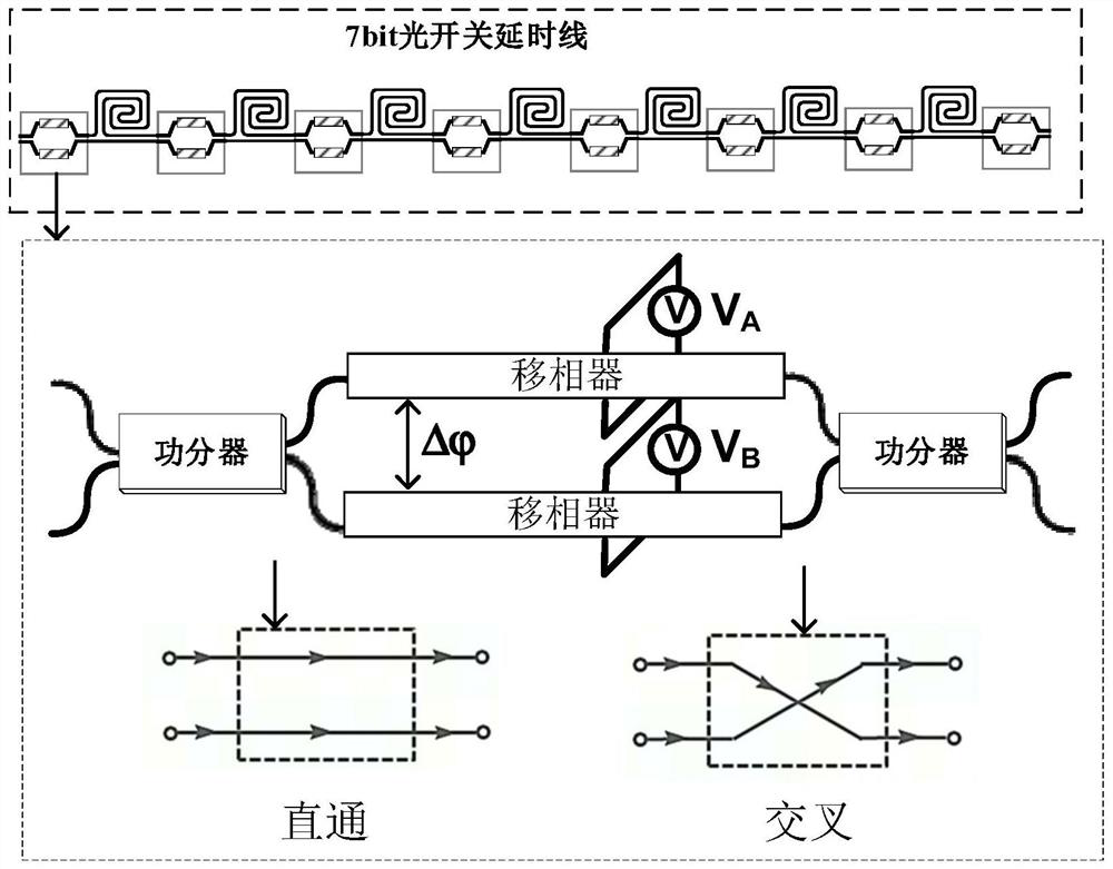
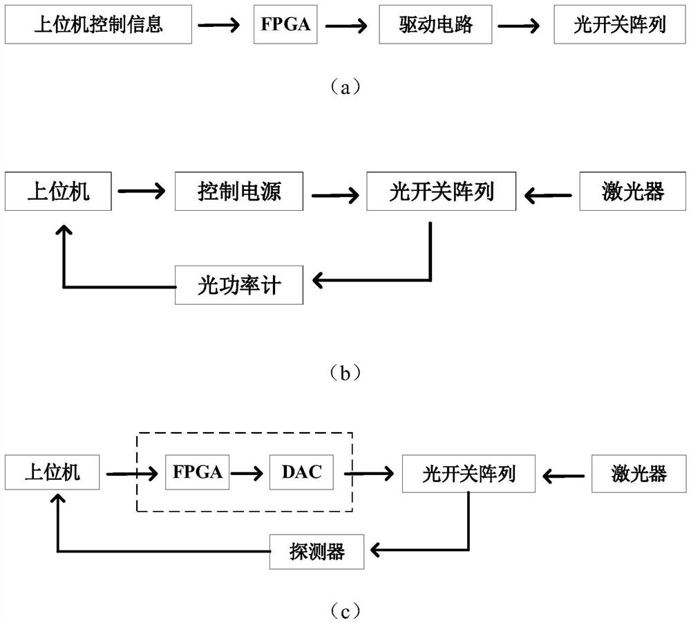
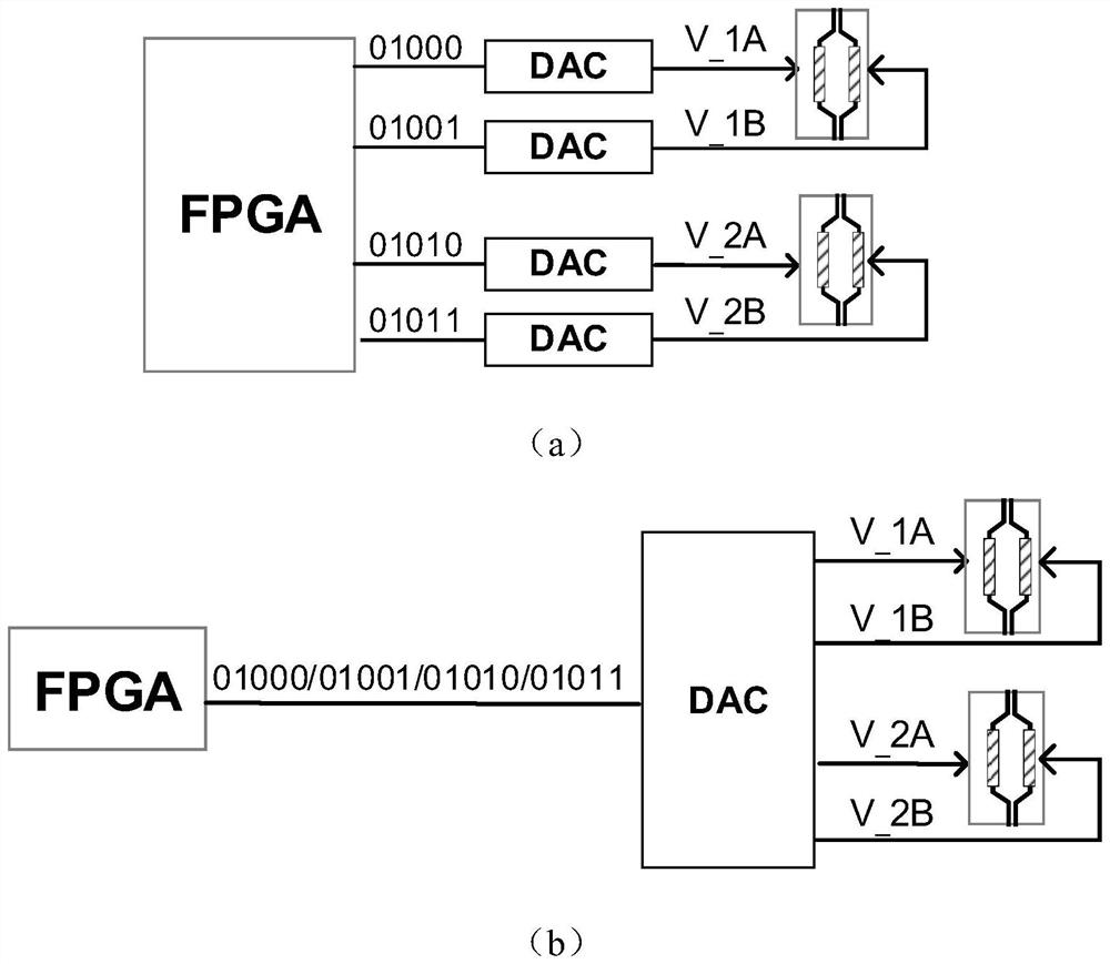
[0034] Such as Figure 4 As shown, the present invention has been proposed for a 7 bit electro-optical switch delay line, a scheme for calibrating and controlling a separation. A calibration control circuit of an optical switch array includes a control circuit, a drive circuit, a feedback calibration circuit, and a microwave photonic link comprising an FPGA, a skew-and-string and an electric switch including two inputs. And two outputs, the microwave photon...


PUM


Abstract

The invention discloses a calibration control circuit of an optical switch array, which comprises a control circuit, a driving circuit, a feedback calibration circuit and a microwave photon link, and is characterized in that the control circuit comprises an FPGA, a serial-to-parallel converter and an electric switch, the electric switch comprises two input ends and two output ends, and the microwave photon link comprises the optical switch array. The optical switch array comprises a plurality of electro-optical switches which are connected in series, each electro-optical switch is of a double-arm MZI structure and comprises two parallel phase shifters, the feedback calibration circuit comprises a multi-channel ADC, the driving circuit comprises a multi-channel DAC, the two parallel phase shifters of each electro-optical switch are connected with two output ends of one electric switch in a one-to-one correspondence mode, and the two output ends of the other electric switch are connected with two output ends of the other electric switch in a one-to-one correspondence mode. Two input ends of each electric switch are respectively and correspondingly connected with an output IO port of the DAC; the method has the advantages that the problems of high cost of the number of components and long control code transmission time in the prior art are solved.

Description

Technical field [0001] The present invention relates to the field of integrated optoelectronics and microelectronics, and more particularly to a calibration control circuit for an optical switch array. Background technique [0002] The optical switch can be switched to the light, and there is a wide range of applications in the field of optical switching networks, light beamforming. Silicon-based Mach - Zeng Del Interference (MZI) Electro-optical switch is an important position in many optical switch categories due to its fast switching speed (switching time <100 ns), low power consumption (<1MW), high integration. [0003] figure 1 A schematic diagram of 2 × 2 (2-in) electro-optical switch is given. The switch adopts a double arm shift Mach, which consists of two power divisors and two phase shifters. When the phase shifter A is biased Va, another shifter B plugged bias 0V, the light is in straight; when the phase shifter A is biased 0V, the phase shifter B is added to th...

Claims


Application Information

Patent Timeline
Patent Type & Authority Applications(China)
IPC IPC(8): H03K17/94
CPCH03K17/943H03K2217/94031
Inventor 高旭东肖士研李泽正梅理朱宇鹏徐珍珠曹继明崇毓华涂路奇
Owner CHINA ELECTRONIC TECH GRP CORP NO 38 RES INST
Why Eureka
Try Eureka