Flat wire stator end twisting device and method thereof

A technology of stator end and flat wire stator, which is applied in the field of twisting device at the end of flat wire stator, can solve the problems of increasing the difficulty of twisting, low efficiency, and failure of twisting, and achieves the effect of saving manpower and improving production efficiency.

Active Publication Date: 2022-04-01
ZHEJIANG ZHONGCHE SHANGCHI ELECTRIC CO LTD
View PDF10 Cites 2 Cited by
  • Summary
  • Abstract
  • Description
  • Claims
  • Application Information

AI Technical Summary

Problems solved by technology

[0004] As the new energy vehicle drive motor stator requires more and more layers of flat wires (currently up to 8 layers), the mold slots corresponding to the stator flat wires have also doubled, and if a wire cannot be inserted into the mold, it will cause The failure of twisting the head, more layers of stator flat wires greatly increases the difficulty of turning the head, and it is required to ensure the accuracy of the insertion line during production
[0005] The existing technical solutions are aimed at a small number of stator flat wire layers, generally 4 layers, and most of them are semi-automatic equipment. When the flat wire is inserted into the mold, manual assistance and confirmation are required, which is inefficient and poor in stability.

Method used


Image

  • Flat wire stator end twisting device and method thereof
  • Flat wire stator end twisting device and method thereof
  • Flat wire stator end twisting device and method thereof

Examples


Embodiment Construction

[0042]Next, the technical solutions in the embodiments of the present invention will be described in connection with the drawings of the embodiments of the present invention, and it is understood that the described embodiments are merely the embodiments of the present invention, not all of the embodiments. Based on the embodiments in the present invention, those of ordinary skill in the art will belong to the scope of the present invention without all other embodiments obtained in the preparation of creative labor.

[0043] In the description of the present invention, it is to be understood that the terms "opening", "upper", "lower", "thickness", "top", "in", "within", "within", "around", etc. Indicates the orientation or positional relationship, is intended to facilitate the description of the present invention and simplified description, rather than indicating or implying that the component or element must have a specific orientation, and therefore cannot be understood as limiti...


PUM


Abstract

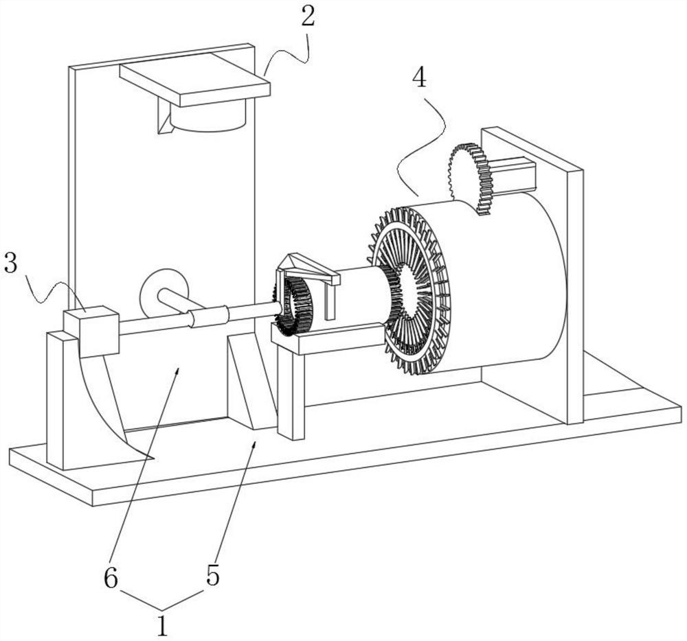
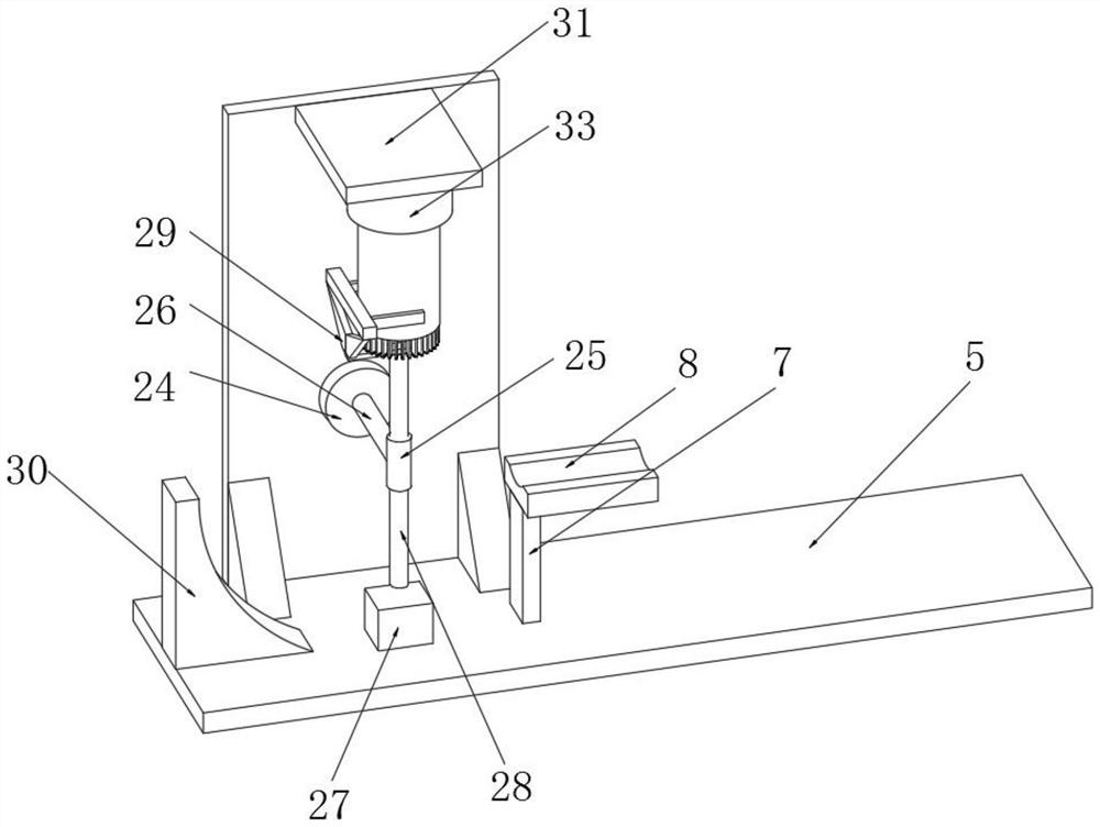
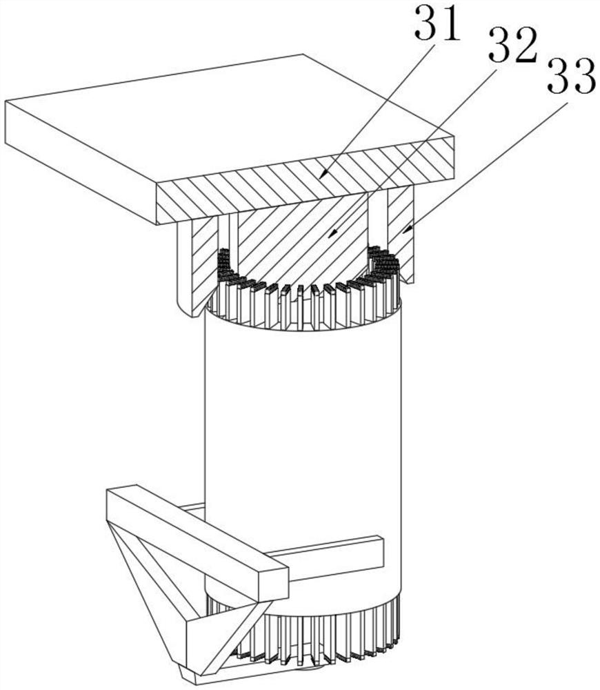
The invention discloses a flat wire stator end twisting device and a method thereof.The flat wire stator end twisting device comprises a rack, the rack is provided with a radial deflection adjusting mechanism, a taking mechanism and a circumferential deflection adjusting mechanism, the rack comprises a base and a side plate, the side plate is vertically installed on the base, the top end of the base is fixedly connected with supporting legs, and the supporting legs are fixedly connected with the side plate. According to the flat wire stator end head twisting device and method, the radial deflection adjusting mechanism is arranged, the radial angle of a flat wire is limited and corrected through the inner ring shaping plate and the outer ring shaping plate, automatic correction of the flat wire bent in the radial direction in a stator is achieved, the working efficiency is improved, and the working efficiency is improved. According to the utility model, the circumferential deflection adjusting mechanism is matched to automatically align the circumferentially bent flat wires in the stator, so that each flat wire can be inserted into the head twisting die, the accuracy of wire insertion is ensured, the qualified rate of head twisting is improved, the manpower is saved, and the production efficiency is improved.

Description

Technical field [0001] The present invention relates to the field of flat wire stator end twist device, and in particular, a flat line stator end twist device and method thereof. Background technique [0002] The stator is a portion of the motor or the stationary station, and the stator consists of three parts: the stator core, the stator winding, and the base. The main role of the stator is to generate a rotating magnetic field, and the main role of the rotor is to cut the magnetine in the rotating magnetic field to generate current. [0003] As the country strongly promotes energy-saving and environmental protection, new energy vehicles have developed rapidly. The drive motor acts as a core component of the new energy vehicle, which is a crucial effect in which the stator of the drive motor is needed to be slurched during the drive motor assembly. [0004] Since the number of flat lines required for the new energy vehicle drive motor stator (currently reaching 8 layers), the mo...

Claims


Application Information

Patent Timeline
Patent Type & Authority Applications(China)
IPC IPC(8): B21F7/00B21D11/10B21D11/14B21D11/22B21D37/10H02K15/02
CPCY02T10/64
Inventor 范庆峰董江东刘小龙崔春宝刘运宝
Owner ZHEJIANG ZHONGCHE SHANGCHI ELECTRIC CO LTD
Why Eureka
Try Eureka