Splitting machine sampling device for gravure production line

A slitting machine and production line technology, applied in the printing field, can solve problems such as eardrum damage, and achieve the effect of ensuring efficiency, easy search and recycling

Active Publication Date: 2022-04-01
ANHUI ANTAI NEW PACKAGE MATERIAL
View PDF6 Cites 0 Cited by
  • Summary
  • Abstract
  • Description
  • Claims
  • Application Information

AI Technical Summary

Problems solved by technology

[0003] The object of the present invention is to provide a kind of slitting machine sampling device used in the gravure printing production line, to solve the existing slitting machine sampling in the above-mentioned background technology The device has the problem of damage to the eardrum caused by manual sampling work for a long time. The invention has the functions of automatic operation, reducing the amount of paper waste and improving production efficiency

Method used


Image

  • Splitting machine sampling device for gravure production line
  • Splitting machine sampling device for gravure production line
  • Splitting machine sampling device for gravure production line

Examples


Embodiment 1

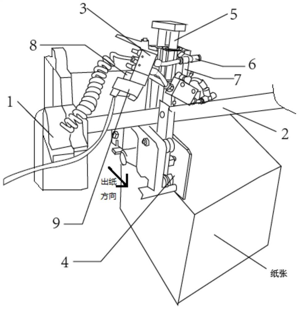
[0032] see Figure 1-8, in the embodiment of the present invention, a kind of slitter sampling device used in gravure printing production line, comprises the slitter 1 that is used for slitting paper 12, and the output end of slitter 1 is provided with receiving table 10, and receiving table A weighing device is installed in the 10, a conveyor belt 11 is arranged on the top of the receiving platform 10, the upper surface of the conveyor belt 11 is used to accept the paper 12, and a base 7 is arranged above one end of the conveyor belt 11 outputting the paper 12, and a The electronic valve 3, the output end of the electronic valve 3 is connected with the gas rod 5, the gas rod 5 is connected with the baffle 4, the gas rod 5 drives the baffle 4 to move up and down; A power interface 9 is provided, and a switch 8 is provided on the power interface 9;

[0033] When the baffle 4 goes down to the maximum stroke, the movement of the paper 12 is blocked and used for the stacking of t...

Embodiment 2

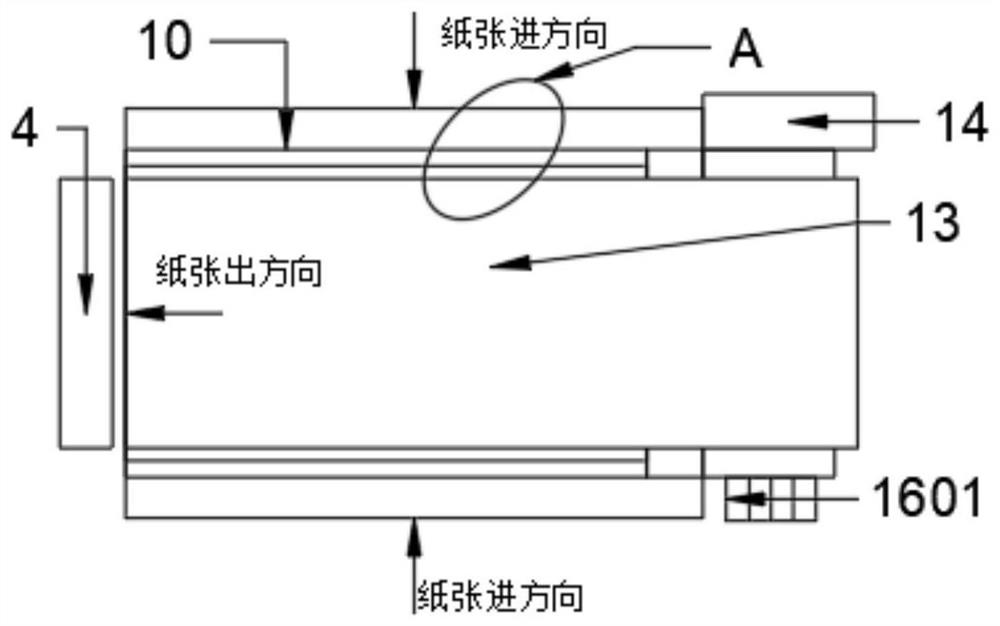
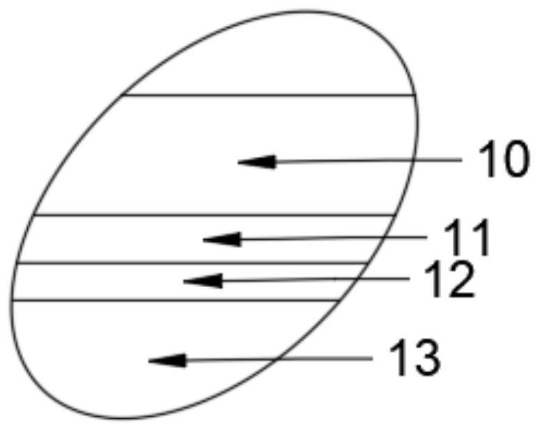
[0035] This embodiment is further improved on the basis of Embodiment 1. This embodiment is a specific implementation of the upper structure of the conveyor belt 11 in Embodiment 1 that accepts the paper stack: a mounting plate 14 is provided above the conveyor belt 11, and the installation A first rotating shaft 15 and a second rotating shaft 16 are installed on the plate 14, an irregular gear 1501 is installed on the outer wall of the first rotating shaft 15, and a rotating gear 1601, an irregular gear 1501 and a rotating gear are installed on the outer wall of the second rotating shaft 16. 1601 meshing, the outer wall of the second rotating shaft 16 is connected with a pressing plate 13, the second rotating shaft 16 drives the pressing plate 13 to rotate, the lower surface of the pressing plate 13 is equipped with a paper stack labeling machine 31a, and the mounting plate 14 is equipped with a fixed block 17, the pressing plate 13 A first elastic member 18a is installed betw...

Embodiment 3

[0038] This embodiment is further improved on the basis of Embodiment 2. This embodiment is a specific implementation of the upper structure of the pressing plate 13 in Embodiment 2: a frame 21 is installed on the upper surface of the pressing plate 13, and a frame 21 is installed on the frame 21. Conveyor belt 22, the outer wall edge of conveyor belt 22 is equipped with mounting block 23, is installed on the mounting block 23 with the sleeve 24 that is perpendicular to the moving direction of conveyor belt 22, is nested with fixed rod 25 that rotates in sleeve 24, and fixed rod 25 is fixedly connected with Connecting plate 26, connecting plate 26 is provided with strip-shaped hole, is nested with connecting rod 27 in the strip-shaped hole, and connecting rod 27 slides in the strip-shaped hole, and connecting rod 27 lower end is fixedly connected with slide plate 20, and slide plate 20 is used for undertaking the first A sheet of paper 12, the first sheet of paper 12 is defined...


PUM


Abstract

The invention discloses a splitting machine sampling device used in a gravure production line. The splitting machine sampling device comprises a splitting machine, and the output end of the splitting machine is provided with a bearing table used for bearing paper; the bearing table is used for stacking a preset number of paper into a paper stack, and a pressing plate and a driving assembly are arranged above the bearing table; the driving assembly drives the pressing plate to press a preset number of paper stacks, and the labeling assembly and the sampling assembly are arranged above the pressing plate; the labeling assembly is used for labeling the sampling paper above the pressing plate; the sampling assembly is used for conveying sampling paper for labeling; after the sampling assembly sucks the sampled paper, the driving assembly drives the pressing plate to be away from the paper stack on the bearing table; and the feeding assembly is used for conveying the paper stacks. The sampling device conveys the labeled sampling paper, the sampling paper is conveyed to the detection position to be detected, and the labeled sampling paper is detected, so that the conditions such as specification quality and the like of paper processing of the splitting machine at different moments are correspondingly reflected.

Description

technical field [0001] The invention relates to the technical field of printing, in particular to a sampling device for a slitting machine used in a gravure printing production line. Background technique [0002] In the printing industry, the sampling of the existing slitting machine requires humans to stand on the slitting machine to carry out the sampling of the paper. In the case of poor sampling, it is easy to cause paper jams; Time-consuming sampling work will lead to damage to the eardrum, and when there is an error in the size and specification of the paper, humans cannot make accurate judgments in time, resulting in a large amount of paper waste. Contents of the invention [0003] The object of the present invention is to provide a slitting machine sampling device used in a gravure printing production line, to solve the problem that the existing slitting machine sampling device in the above-mentioned background technology has artificially performed sampling work fo...

Claims


Application Information

Patent Timeline
Patent Type & Authority Applications(China)
IPC IPC(8): B41F19/00B41F21/00B41F33/00G01G19/52
Inventor 熊国高李俊杰朱国良
Owner ANHUI ANTAI NEW PACKAGE MATERIAL
Why Eureka
Try Eureka