Marine container air conditioner

A container ship and air-conditioning technology, applied in ship construction, ship parts, transportation and packaging, etc., can solve the problems of energy waste, power consumption, high operating costs, etc., and achieve the effect of saving power consumption and reducing operating costs

Active Publication Date: 2022-05-17
海英荷普曼船舶设备(常熟)有限公司
View PDF0 Cites 0 Cited by
  • Summary
  • Abstract
  • Description
  • Claims
  • Application Information

AI Technical Summary

Problems solved by technology

[0003] Today's container ships below 100,000 tons have a draft of more than 10 meters. The bottom of the ship is in the constant temperature layer of the sea. Hundreds of thousands of kilowatt-power auxiliary engines on board are burning oil to generate electricity. The power consumption and operating cost are relatively high, and the operation of the power generation equipment in the fuel-fired power generation room in the ship will generate a lot of heat. If the power generation equipment in the fuel-fired power generation room runs for a long time and generates a large amount of heat without cooling down, its service life will be shortened At the same time, the existing container ships usually cannot utilize the heat generated by the power generation equipment in the fuel-fired power generation room, resulting in a large amount of energy waste
[0004] Therefore, it is necessary to design a system that can automatically use constant-temperature seawater for refrigeration according to the temperature in the cabin, aiming at the shortcomings of the existing technology that consume a large amount of electric energy to supply the air-conditioning system and the large amount of heat generated by the operation of the power generation equipment in the fuel-fired power generation room, resulting in energy waste. Sea container marine air conditioner that can effectively cool down the power generation equipment in the fuel-fired power generation room and fully utilize the heat generated by the power generation equipment in the fuel-fired power generation room

Method used


Image

  • Marine container air conditioner
  • Marine container air conditioner
  • Marine container air conditioner

Examples


Embodiment 1

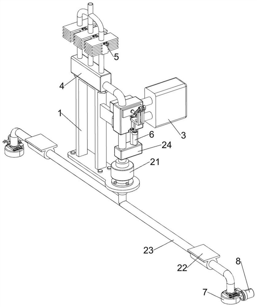
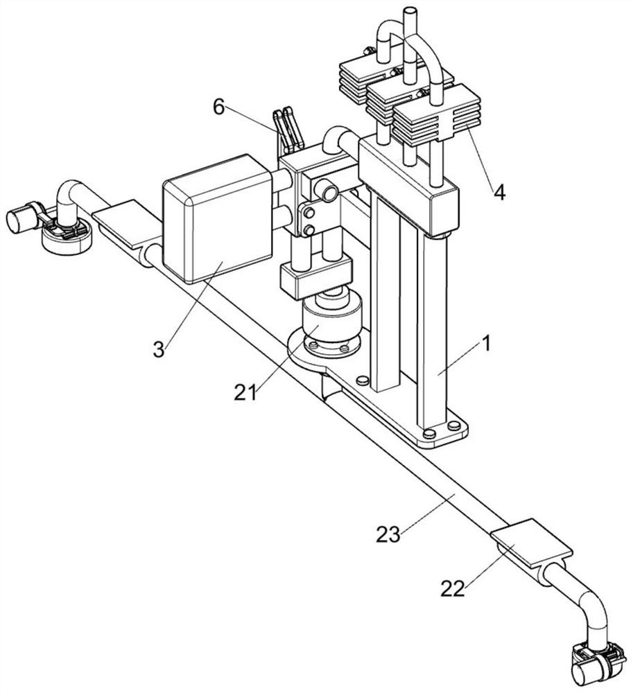
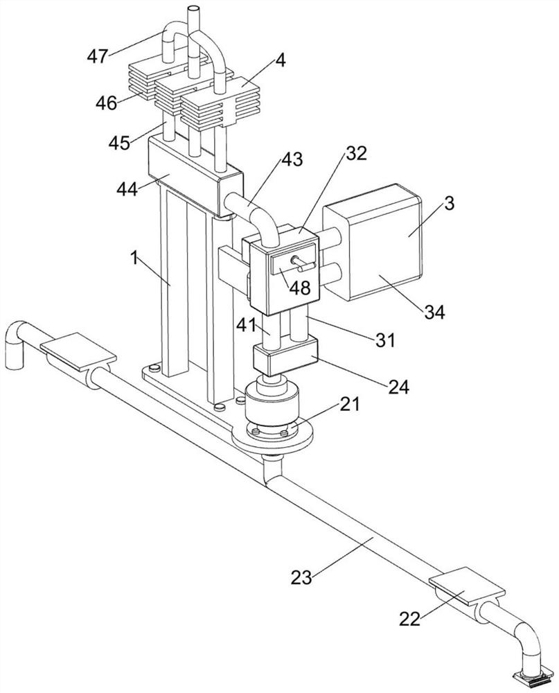
[0043] Ocean container marine air conditioner, such as figure 1 , figure 2 , image 3 , Figure 4 , Figure 5 with Image 6 As shown, it includes a fixed installation frame 1, a water pump 21, a perforated support frame 22, a T-shaped water suction pipe 23, a shunt pipe 24, a fuel-fired power generation room cooling assembly 3 and an air temperature adjustment assembly 4, and the top of the fixed installation frame 1 is fixed with Suction pump 21. Suction pump 21 is used to pump constant temperature seawater upwards. A pair of perforated support frames 22 are fixedly connected to the bottom of the hull. A T-shaped water suction pipe 23 is fixedly connected between the two perforated support frames 22. The T-shaped water suction pipe 23 is used to transport constant temperature seawater, T-shaped water pipe 23 passes through the fixed mounting frame 1, T-shaped water pipe 23 is connected with the bottom of the water pump 21, and a shunt pipe 24 is connected above the water...

Embodiment 2

[0050] On the basis of Example 1, such as Figure 7 As shown, it also includes a temperature-sensing adjustment assembly 5. The temperature-sensing adjustment assembly 5 is arranged on the shunt cavity 44. The temperature-sensing adjustment assembly 5 is used to sense the temperature in each compartment of the cabin in real time. The temperature-sensing adjustment assembly 5 includes an electromagnetic The valve 51 and the temperature sensor 52 are fixed with three electromagnetic valves 51 in a linear distribution manner in the top of the diversion cavity 44. The electromagnetic valves 51 are used to control the circulation of seawater in the diversion tube 45. The adjacent electromagnetic valves 51 and the guide tube The flow pipe 45 is fixedly connected, and the right side of the temperature regulator 46 is fixedly connected with a temperature sensor 52, and the temperature sensor 52 is used to sense the temperature in the cabin compartment to control the switch of each elec...

Embodiment 3

[0053] On the basis of Example 2, such as Figure 8 As shown, it also includes a switching assembly 6, which is arranged on the right side outside the support block 32, and the switching assembly 6 is used to automatically switch the heating and cooling. The switching assembly 6 includes a T-shaped opening frame 61, an electric push rod 62 , slide rail frame 63 and slotted limit frame 64, the outside right side of the support block 32 is fixedly connected with a T-shaped hole frame 61, and the T-shaped hole frame 61 is fixedly equipped with an electric push rod 62, and the outside right side of the support block 32 Affixed with slide rail frame 63, one end of electric push rod 62 telescopic shafts is affixed with slotted limit frame 64, and slotted limit frame 64 top has a pair of oblique chute (in Figure 8 shown in ), the slotted limit frame 64 is used to pull out or push in the T-shaped push rod 410, instead of manually pulling out or pushing in the T-shaped push rod 410, t...


PUM


Abstract

The present invention relates to the technical field of container ships at sea, in particular to an air conditioner for container ships at sea, including a fixed installation frame, a water pump, a perforated support frame, a T-shaped water pipe, etc.; There is a pair of perforated supporting frames, and a T-shaped water pipe is fixedly connected between the two perforated supporting frames. When it is necessary to heat up the cabin, the constant-temperature seawater will flow through the radiator, and the seawater will exchange heat with the fuel-fired power generation through the radiator, so that the temperature of the constant-temperature seawater will rise, and the heated seawater will then exchange heat with the temperature regulator, which can make the The temperature in the cabin rises, so that the heat from the constant-temperature seawater and fuel-fired power generation room can be used to heat up the cabin, saving power consumption and reducing operating costs; when the cabin needs to be cooled, the constant-temperature seawater will directly communicate with the temperature regulator The heat exchange makes the constant temperature sea water take away the heat in the cabin, thereby reducing the temperature in the cabin.

Description

technical field [0001] The invention relates to the technical field of sea container ships, in particular to an air conditioner for sea container ships. Background technique [0002] Container ship is a new type of ship, its loading and unloading efficiency is extremely high, the time of docking in port is greatly shortened, and the cargo damage during transportation and loading and unloading is reduced, so it has been developed rapidly. Container ships have no inner deck, and the engine room is located at the stern. The hull is actually a huge warehouse. Container ships usually dock at special cargo terminals, and are loaded and unloaded with special large cranes on the terminals. The efficiency can reach 1000-2400 tons per hour, compared with Ordinary general cargo ships are 30-70 times taller and are widely used in the modern shipping industry. [0003] Today's container ships below 100,000 tons have a draft of more than 10 meters. The bottom of the ship is in the consta...

Claims


Application Information

Patent Timeline
Patent Type & Authority Patents(China)
IPC IPC(8): B63J2/12
CPCB63J2/12B63J2002/125Y02T70/50
Inventor 曹爱君眭建
Owner 海英荷普曼船舶设备(常熟)有限公司
Why Eureka
Try Eureka