Physical cooling equipment and method for incinerator for household garbage incineration treatment

A technology of domestic waste incineration and physical cooling, applied in the field of incinerators, can solve the problems of temperature damage of waste combustion fire, inability to control the temperature of the grate effectively, and achieve effective and rapid cooling effect.

Pending Publication Date: 2022-04-01
黄海浩
View PDF0 Cites 0 Cited by
  • Summary
  • Abstract
  • Description
  • Claims
  • Application Information

AI Technical Summary

Problems solved by technology

[0004] In summary, the present invention provides an incinerator physical cooling device and method for domestic waste incineration treatment, which is used to solve the problem that the temperature of the grate in the furnace of the existing incinerator cannot be effectively controlled, resulting in internal garbage Excessive combustion fire is easy to cause damage due to excessive temperature

Method used


Image

  • Physical cooling equipment and method for incinerator for household garbage incineration treatment
  • Physical cooling equipment and method for incinerator for household garbage incineration treatment
  • Physical cooling equipment and method for incinerator for household garbage incineration treatment

Examples


Embodiment approach

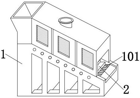
[0026] Preferred implementation mode: the fixed grate 101 includes a cooling groove 1011, a deflecting plate 1012 and an abutment groove 1013, the cooling groove 1011 is a rectangular groove in the middle of the fixed grate 101, and the deflecting plate 1012 is embedded in the middle through a circular shaft. The rectangular plate is arranged at the bottom end of the middle part of the cooling tank 1011, and the contact groove 1013 is a rectangular groove extending obliquely near the bottom end of one side of the deflection plate 1012.

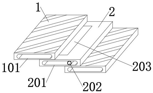
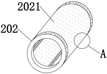
[0027] Preferred implementation mode: the movable grate 2 includes a water flow tank 201, a water storage shaft 202 and a flipping plate 203, the water flow tank 201 is a rectangular groove in the middle of the movable fire grate 2, and the water storage shaft 202 is a water flow tank with the same diameter as the water flow tank. 201 is a hollow circular shaft fitted with a width, and one end of the water storage shaft 202 communicates with an...


PUM


Abstract

Physical cooling equipment of an incinerator for household garbage incineration treatment comprises a main body, fixed fire grates and movable fire grates, the fixed fire grates are embedded in the middle of the main body, the movable fire grates are embedded between the fixed fire grates, deflection plates are embedded in the middles of the fixed fire grates through the bottom ends of cooling grooves, and water storage shafts are embedded in water flow grooves in the middles of the movable fire grates. A turning plate is embedded in the middle of the top end of the movable fire grate. According to the device, when the movable fire grate moves repeatedly, water flow can be injected into the water storage shaft to be sprayed to the inner wall of the movable fire grate, so that the core temperature of the movable fire grate is physically reduced and controlled, and the situation that the movable fire grate is damaged due to the fact that a certain combustion-supporting material is contained in combusted objects is avoided. The fire grate is easy to damage due to overlarge fire behavior and overhigh temperature; and meanwhile, the cooling is slow after the fire grate is used.

Description

technical field [0001] The present invention relates to the technical field of incinerators, and more specifically relates to the technical field of an incinerator physical cooling device and method for domestic waste incineration treatment. Background technique [0002] In the process of burning garbage in the existing incinerator, the temperature in the inner furnace cannot be effectively controlled. Therefore, when burning some garbage with combustion-supporting materials, the fire will be too large, and the internal temperature will be too high. Let the grate be damaged, and at the same time, the temperature of the grate can only wait for its natural heat dissipation after use, so that its heat dissipation efficiency is too low. Contents of the invention [0003] (1) Technical issues [0004] In summary, the present invention provides an incinerator physical cooling device and method for domestic waste incineration treatment, which is used to solve the problem that th...

Claims


Application Information

Patent Timeline
Patent Type & Authority Applications(China)
IPC IPC(8): F23G5/44F23G5/00F23H3/02F23H11/06F23H11/24
Inventor 黄海浩
Owner 黄海浩
Why Eureka
Try Eureka