Supercharge Your Innovation With Domain-Expert AI Agents!

Ophthalmologic operating bed

An ophthalmic surgery and bed body technology, applied in the field of medical devices, can solve problems such as inconvenience of operation, doctor's operation error, offset of bed and body position, etc., to achieve the effect of convenient operation, improved success rate, and compact layout

Pending Publication Date: 2022-04-05
TAICANG KANGHUI TECH DEV
View PDF0 Cites 0 Cited by
  • Summary
  • Abstract
  • Description
  • Claims
  • Application Information

AI Technical Summary

Problems solved by technology

[0004] At present, an ophthalmic operating bed includes a bed support structure, a chassis with shifting wheels, and a lifting structure. The bed support structure includes a head support unit, a back support unit, and a leg support unit, and the relative rotation between the three is adjusted. The lifting structure is used to adjust the height of the bed support structure relative to the chassis. However, there are the following defects in the existing adjustment method: 1) When turning over and adjusting, as the turning angle changes, the formed support position will move. Therefore, After flipping and adjusting, a good support effect cannot be formed. At the same time, the patient's body needs to be effectively shifted to position the leg comfortably at the surgical angle. It will cause the deviation of the position of the bed and the body, which will affect the accuracy of the operation; 2) After turning over, if the push handle is not folded separately, it will form an obstacle and affect the accurate operation of the doctor; 3) After the lifting adjustment, Especially with the upward movement of the center of gravity, if the corresponding position restrictions cannot be implemented, there will be a movable space. In this way, during the operation, the change of the position or angle will cause errors in the operation of the doctor during the operation, affecting the operation of the doctor. success rate of surgery

Method used


Image

  • Ophthalmologic operating bed
  • Ophthalmologic operating bed
  • Ophthalmologic operating bed

Examples


Embodiment Construction

[0047] In order to make the above-mentioned purpose, features and advantages of the present application more obvious and understandable, the specific implementation manners of the present application will be described in detail below in conjunction with the accompanying drawings. In the following description, numerous specific details are set forth in order to provide a thorough understanding of the application. However, the present application can be implemented in many other ways different from those described here, and those skilled in the art can make similar improvements without departing from the connotation of the present application, so the present application is not limited by the specific embodiments disclosed below.

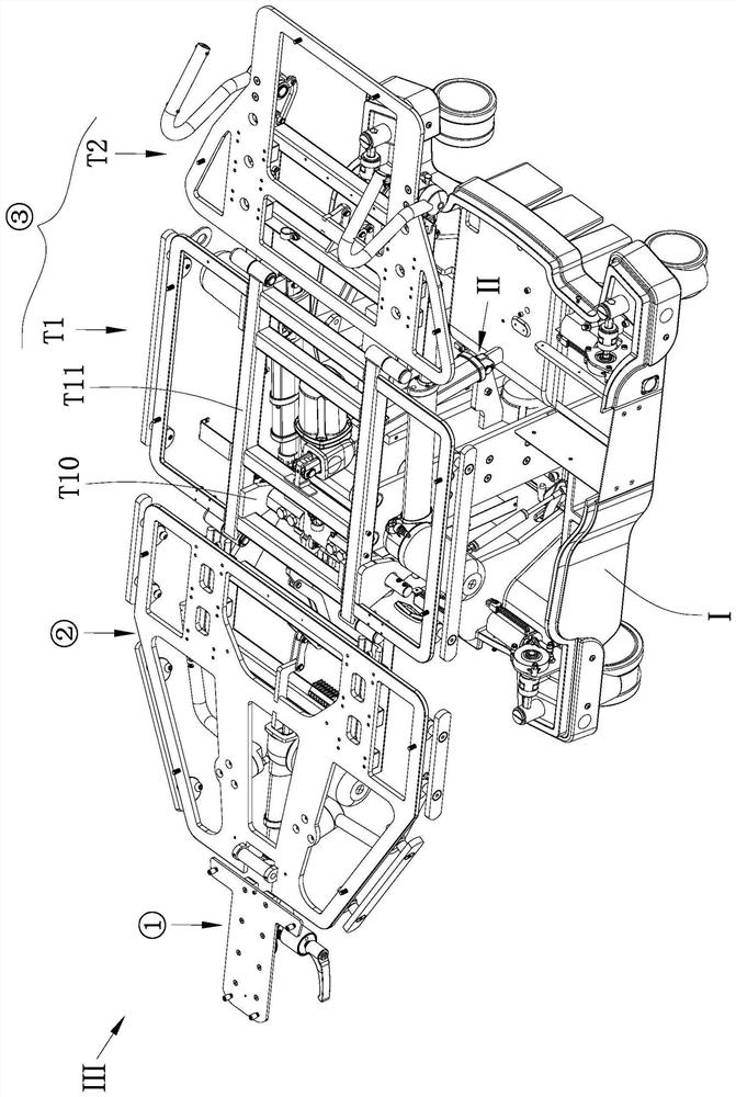
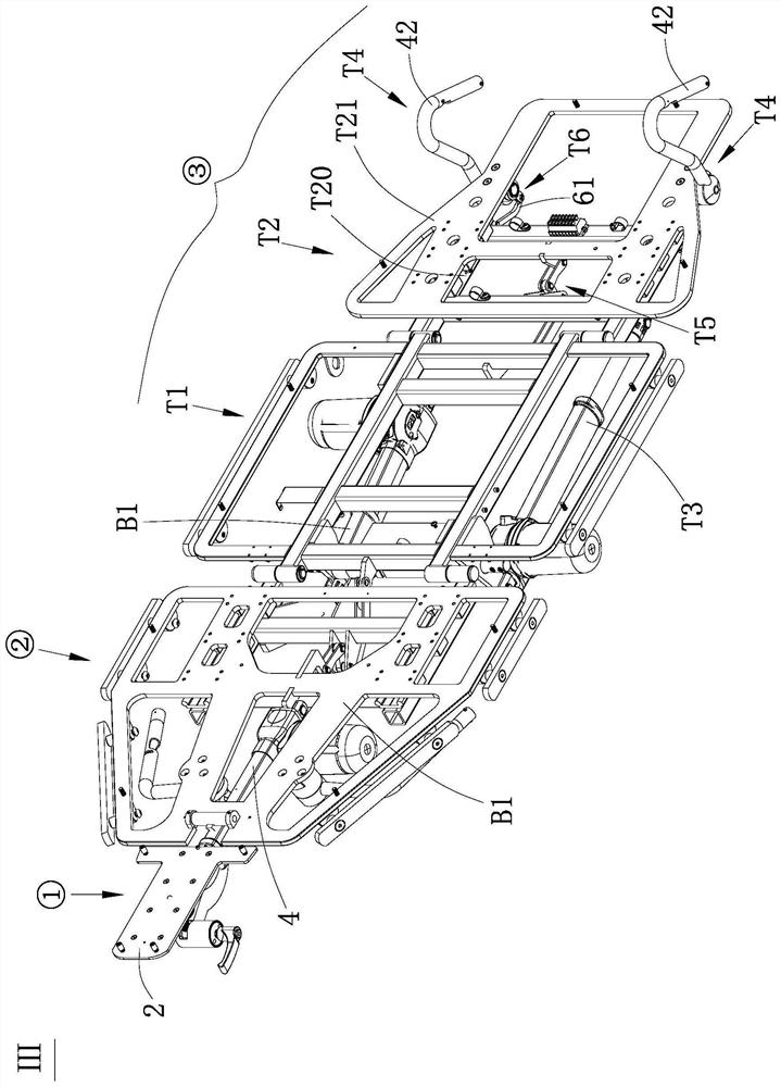
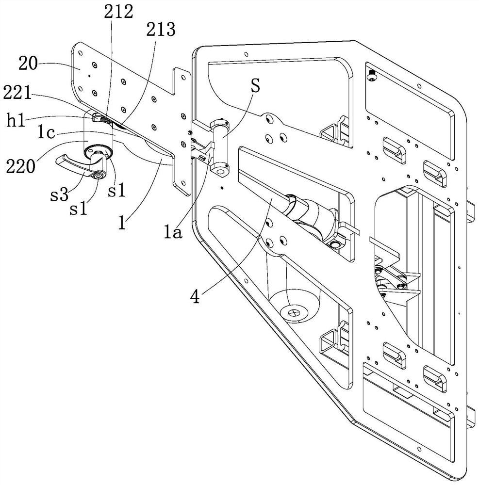
[0048] Such as figure 1 As shown, the ophthalmic operating bed of this embodiment includes a chassis I with wheels, a lifting structure II, and a bed support structure III, wherein the bed support structure III includes a head support unit ① and a back...


PUM


Abstract

The ophthalmic operating bed comprises a chassis, a lifting structure and a bed body supporting structure, and the bed body supporting structure comprises a head supporting unit, a back supporting unit and a leg supporting unit which are rotationally connected from the front end and the rear end. The leg supporting unit comprises a thigh bracket and a shank bracket which are rotationally connected, a driving part for driving the shank bracket to turn over, and push handles arranged on the two sides of the shank bracket, the thigh bracket comprises a supporting seat and a turning seat arranged on the supporting seat in a manner of turning over around the horizontal direction, and the lifting structure comprises a telescopic rod; wherein the two end parts of the telescopic rod are arranged between the supporting seat and the chassis. On one hand, under leg overturning and lifting adjustment and locking limiting, angle adjustment can be implemented without body displacement, and effective support is formed; and on the other hand, the push handle can be turned, folded or unfolded synchronously during leg turning, so that the surgical operation is facilitated, and the success rate of the surgery is increased.

Description

technical field [0001] The invention belongs to the field of medical instruments, and in particular relates to an ophthalmic operating bed. Background technique [0002] As we all know, ophthalmology is a subject that studies diseases that occur in the visual system, including the eyeball and its associated tissues. It generally studies various ophthalmic diseases such as vitreous, retinal diseases, optometry, glaucoma, optic neuropathy, and cataracts. [0003] However, patients undergoing eye surgery generally suffer from serious diseases that affect eye vision. During eye surgery, in order to ensure the smooth progress and success rate of the operation, the patient needs to make an appropriate posture for the operation method , It is convenient for doctors to perform examination and operation on patients. [0004] At present, an ophthalmic operating bed includes a bed support structure, a chassis with shifting wheels, and a lifting structure. The bed support structure inc...

Claims


Application Information

Patent Timeline
IPC IPC(8): A61G13/06A61G13/08A61G13/10A61G13/12A61F9/007
Inventor 陈宇豪杨楚
Owner TAICANG KANGHUI TECH DEV
Features
  • R&D
  • Intellectual Property
  • Life Sciences
  • Materials
  • Tech Scout
  • Unparalleled Data Quality
  • Higher Quality Content
  • 60% Fewer Hallucinations
Learn More