Stamping die for automobile part machining

A technology for stamping dies and auto parts, applied in the field of die stamping, which can solve the problems of cumbersome loading and unloading of devices, large manual labor, and low work efficiency, and achieve the effects of reducing manual labor, high practicability, and convenient operation and use

Pending Publication Date: 2022-04-05
上海乾驰模具有限公司
View PDF0 Cites 2 Cited by
  • Summary
  • Abstract
  • Description
  • Claims
  • Application Information

AI Technical Summary

Problems solved by technology

[0003] The traditional device for stamping dies sometimes needs to be replaced according to the different parts to be processed. However, it is very inconvenient to replace the traditional device, requiring manual disassembly and installation, and the work efficiency is low. At the same time, the traditional device The loading and unloading is cumbersome, the amount of manual labor is large, and the practicability is not high

Method used


Image

  • Stamping die for automobile part machining
  • Stamping die for automobile part machining
  • Stamping die for automobile part machining

Examples


Embodiment 1

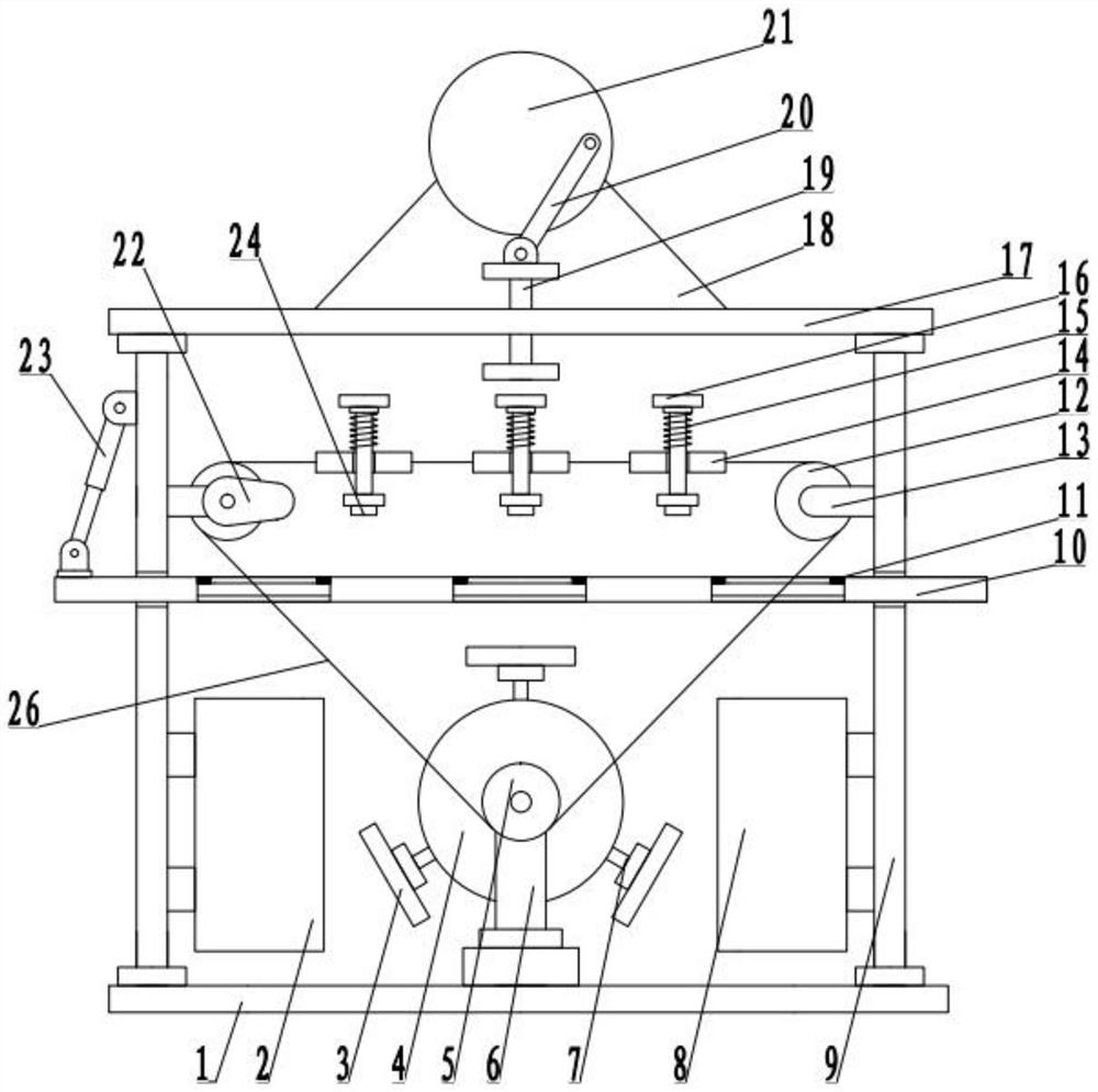
[0025] see Figure 1-4 , a stamping die for processing auto parts, including a base plate 1, and also includes:

[0026] The struts 9 fixedly arranged on both sides of the bottom plate 1, the top of the struts 9 are fixedly connected to the top plate 17;

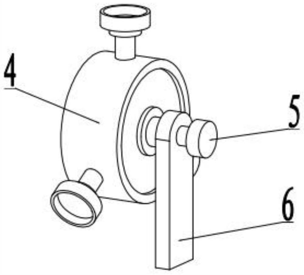
[0027] The conversion mechanism arranged between the poles 9 includes a mounting rod 6, which is fixedly connected to the bottom plate 1, and one side of the mounting rod 6 is connected to the switching disc 4 in rotation, and the rotating shaft of the switching disc 4 is connected to the mounting rod on one side in the axial direction. 6. The side wall is rotatably connected to the installation wheel 5, and the axial side of the rotation shaft of the installation wheel 5 is fixedly connected to the rotation shaft of the conversion disc 4. The conversion disc 4 is fixedly connected to the suction cup 7, and there are multiple suction cups. The mold plate 3 is fixedly adsorbed, the side wall of the installation rod 6 is fixe...

Embodiment 2

[0031] see Figure 1-4 , the other content of this embodiment is the same as that of Embodiment 1, the difference is that: the telescopic assembly includes a limit block 14, the limit block 14 is fixedly arranged on the transmission belt 26, and the piston is slid through the limit block 14 The rod 16 and the piston rod 16 are T-shaped structures. The elastic member 15 is sheathed on the piston rod 16 . A stamping die is provided at the bottom of the piston rod 16 , and a magnetic head 24 is fixedly provided on the stamping die.

[0032] The feeding mechanism includes a feeding plate 10, the two ends of the feeding plate 10 are slidably connected with the pole 9, the feeding plate 10 is provided with a bearing groove 27, and the two sides of the inner wall of the bearing groove 27 are fixedly connected to the magnet block 11, and the pole 9 The side wall is hinged with an electric telescopic rod 23, and one end of the electric telescopic rod 23 is hinged with the feeding plate...


PUM


Abstract

The invention discloses a stamping die for automobile part machining, and relates to the technical field of die stamping, the stamping die comprises a bottom plate and further comprises supporting rods arranged on the two sides of the bottom plate, and the tops of the supporting rods are fixedly connected with a top plate; the switching mechanism is arranged between the supporting rods and comprises a mounting rod, the mounting rod is fixedly connected with the bottom plate, one side of the mounting rod is rotatably connected with a switching disc, the side wall of the mounting rod on one axial side of a rotating shaft of the switching disc is rotatably connected with a mounting wheel, one axial side of the rotating shaft of the mounting wheel is fixedly connected with the rotating shaft of the switching disc, and the switching disc is fixedly connected with a suction cup. A mold plate is fixedly adsorbed on the suckers, the side walls of the mounting rods are fixedly connected with positioning rods, one sides of the positioning rods are rotationally connected with rotating wheels, a transmission belt is arranged between the rotating wheels and the mounting wheels, a telescopic assembly is arranged on the transmission belt, and the feeding mechanism is arranged between the mounting rods and used for feeding and discharging. The driving mechanism is arranged above the top plate and used for driving the telescopic assembly below to conduct stamping.

Description

technical field [0001] The invention relates to the technical field of die stamping, in particular to a stamping die for processing automobile parts. Background technique [0002] Auto parts processing is the unit that constitutes the overall processing of auto parts and the products that serve the processing of auto parts. As the foundation of the auto industry, auto parts are a necessary factor to support the sustainable and healthy development of the auto industry. Usually need to use the mold. [0003] The traditional device for stamping dies sometimes needs to be replaced according to the different parts to be processed. However, when the traditional device is replaced, it is very inconvenient, requiring manual disassembly and installation, and the work efficiency is low. At the same time, the traditional device Loading and unloading is relatively cumbersome, the amount of manual labor is large, and the practicability is not high. Contents of the invention [0004] ...

Claims


Application Information

Patent Timeline
Patent Type & Authority Applications(China)
IPC IPC(8): B21D37/10B21D45/04
Inventor 盛英杰卫平
Owner 上海乾驰模具有限公司
Why Eureka
Try Eureka