Tool trolley with turnable and fixed tool apron for five-axis machining center

A five-axis machining center, cutting tool technology, applied in the direction of manufacturing tools, metal processing equipment, metal processing machinery parts, etc., can solve the problems of tool damage, stabbing staff, easy cuts, etc.

Pending Publication Date: 2022-04-05
朱海青
View PDF0 Cites 0 Cited by
  • Summary
  • Abstract
  • Description
  • Claims
  • Application Information

AI Technical Summary

Problems solved by technology

[0005] In order to overcome the existing knife trolley, the knives are placed straight on the knife seat, the sharp knives are directly exposed, without any safety protection, it is extremely easy to cut and stab the staff, and the knives are not protected, resulting in The damage of the tool and the decrease of the accuracy of the tool will eventually affect the production progress and product accuracy. The invention provides a tool car with a tool seat that can be turned over and fixed for a five-axis machining center.

Method used


Image

  • Tool trolley with turnable and fixed tool apron for five-axis machining center
  • Tool trolley with turnable and fixed tool apron for five-axis machining center
  • Tool trolley with turnable and fixed tool apron for five-axis machining center

Examples


Embodiment 1

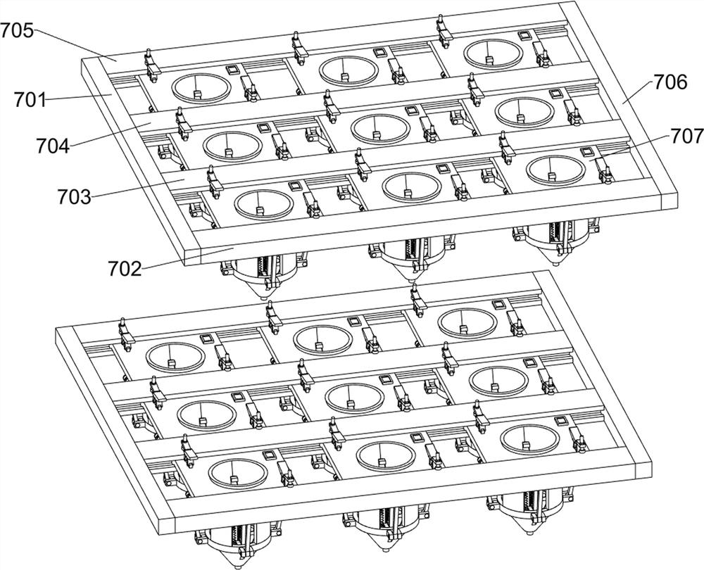
[0040] A tool car with a reversible and fixed tool seat for a five-axis machining center, such as Figure 1-3 As shown, it includes a vehicle frame 1, a first handle 2, a second handle 3, a first control panel 4, a first storage box 5, a turning mechanism 6, a storage mechanism 7, a cleaning mechanism 8, a first collection box 9, a third The handle 10 and the first universal wheel 11; the upper left side of the vehicle frame 1 is provided with the first handle 2 and the second handle 3 in turn; the upper left side of the vehicle frame 1 is installed with the first control panel 4; the upper left side of the vehicle frame 1 The first storage box 5 is installed; the interior of the vehicle frame 1 is provided with an overturning mechanism 6; the upper part of the vehicle frame 1 is fixedly connected with the cleaning mechanism 8; the lower part of the vehicle frame 1 is provided with a first collection box 9; A set of first universal wheels 11 are provided; the turning mechanism...

Embodiment 2

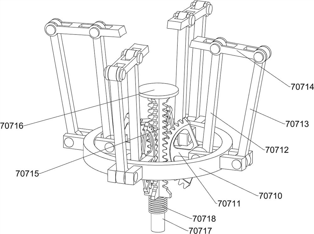
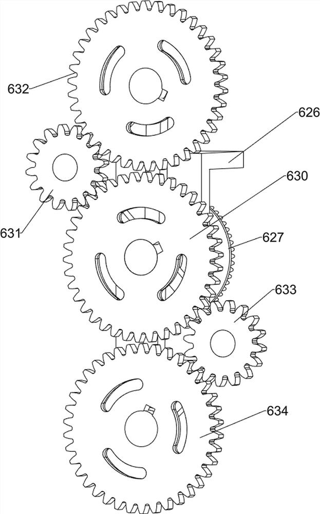
[0043] On the basis of Example 1, such as figure 1 and Figure 4-19As shown, the turning mechanism 6 includes a first support plate 601, a first motor 602, a first bevel gear 603, a second bevel gear 604, a first transmission rod 605, a first support frame 606, a third bevel gear 607, a first Four bevel gears 608, the second transmission rod 609, the fifth bevel gear 610, the second support frame 611, the sixth bevel gear 612, the first connecting frame 613, the third transmission rod 614, the first straight gear 615, the second straight gear Gear 616, third spur gear 617, fourth spur gear 618, fifth spur gear 619, seventh bevel gear 620, fourth transmission rod 621, eighth bevel gear 622, ninth bevel gear 623, fifth transmission rod 624 , the tenth bevel gear 625, the third support frame 626, the eleventh bevel gear 627, the second connecting frame 628, the sixth transmission rod 629, the sixth spur gear 630, the eighth spur gear 631, the ninth spur gear 632, The tenth spur...


PUM


Abstract

The invention relates to the field of tool trolleys, in particular to a tool trolley with a tool apron capable of being fixed in a turnover mode for a five-axis machining center. The technical problems that according to an existing tool trolley, a tool is straightly placed on a tool apron, the sharp tool is directly exposed outside, no safety protection exists, workers are extremely prone to being cut and stabbed, the tool is damaged due to the fact that the tool is not protected, the precision of the tool is reduced, and finally the production schedule and the product precision are affected are solved. According to the technical scheme, the tool trolley with the turnable and fixed tool apron for the five-axis machining center comprises a trolley frame, a first storage box, a turnover mechanism and the like; a first storage box is mounted above the left side of the frame; and a turnover mechanism is arranged in the frame. According to the tool trolley, the two sets of storage mechanisms are overturned through the overturning mechanism, when the tool trolley is not used, tools are stored in the tool trolley, when the tool trolley is used, the tools are exposed out of the tool trolley through the storage mechanisms, and workers can conveniently store and take out the tools from the storage mechanisms.

Description

technical field [0001] The invention relates to the field of tool trolleys, in particular to a tool trolley with a reversible and fixed tool seat for a five-axis machining center. Background technique [0002] There are many products processed by the machining center with high precision, and there are many types of cutting tools used, which require very high precision and are expensive. In order to be able to centralize and access all kinds of tools for convenience, tool carts are generally used on site to store tools commonly used on lathes. [0003] The existing knife trolley places the knives straight on the knife seat, and the sharp knives are directly exposed without any safety protection, so it is extremely easy to cut and stab the staff, and the staff who are cut and stabbed may have The risk of tetanus infection, and if the tool is not protected, it will cause damage to the tool, and the accuracy of the tool will decrease, which will eventually affect the production...

Claims


Application Information

Patent Timeline
IPC IPC(8): B23Q13/00
CPCY02P70/10
Inventor 朱海青
Owner 朱海青
Why Eureka
Try Eureka