Acidic electrolyzed oxidizing water generator electrolytic bath and use method thereof

A technology for oxidizing potential water and acidic water, which is applied in the field of electrolytic cells, can solve the problems of electrolytic unit solution impact, manual cleaning troubles, and affecting electrolysis effects, etc., and achieve the effects of short development cycle, reduced maintenance costs, and improved efficiency

Active Publication Date: 2022-04-05
武汉丽辉新技术有限公司
View PDF12 Cites 1 Cited by
  • Summary
  • Abstract
  • Description
  • Claims
  • Application Information

AI Technical Summary

Problems solved by technology

[0003] In order to increase the amount of acidic oxidation potential water generated, usually multiple unit electrolytic cells are arranged side by side, and then directly connected through conduits. Since the electrolysis conditions of different electrolytic cells are different, direct connection between different electrolytic cells will affect the adjacent cells. The solution of the electrolysis unit causes impact, which in turn affects its electrolysis effect. At the same time, the existing tap water softening process cannot completely remove calcium ions and magnesium ions in tap water, so that in the long-term electrolysis process, it will still be generated in the electrolytic cell. The scale containing calcium and magnesium ions adheres to the inner wall of the electrolytic cell. These scales are insoluble in acidic solution, and manual cleaning is troublesome.

Method used


Image

  • Acidic electrolyzed oxidizing water generator electrolytic bath and use method thereof
  • Acidic electrolyzed oxidizing water generator electrolytic bath and use method thereof
  • Acidic electrolyzed oxidizing water generator electrolytic bath and use method thereof

Examples


Embodiment Construction

[0027] The technical solutions in the embodiments of the present invention will be clearly and completely described below with reference to the accompanying drawings in the embodiments of the present invention. Obviously, the described embodiments are only a part of the embodiments of the present invention, but not all of the embodiments. Based on the embodiments of the present invention, all other embodiments obtained by those of ordinary skill in the art without creative efforts shall fall within the protection scope of the present invention.

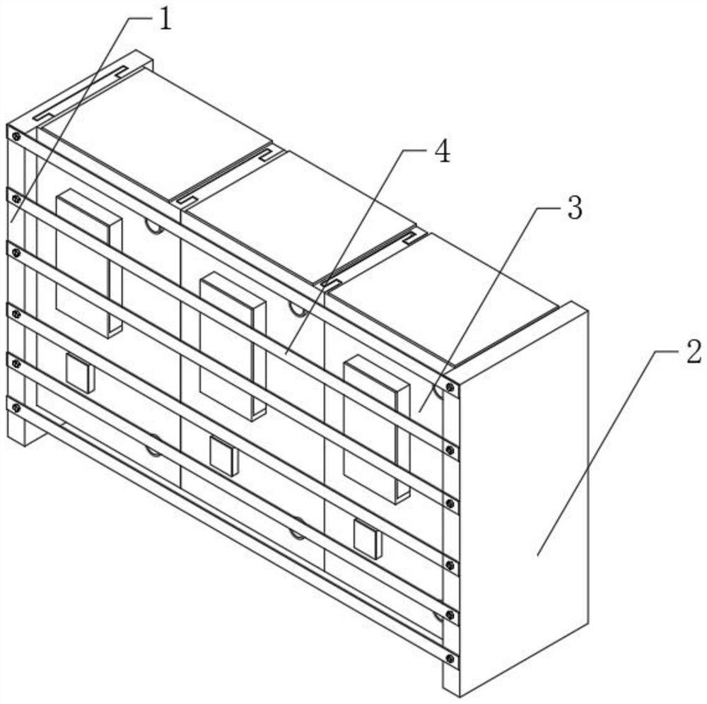
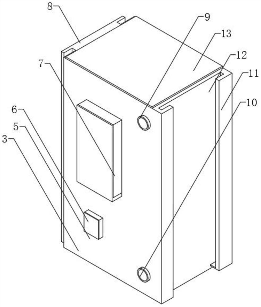
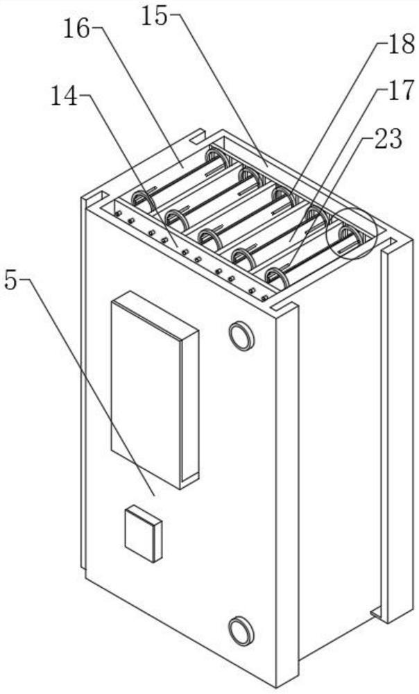
[0028] see Figure 1-5 , the present invention provides a technical scheme of an acid oxidation potential water generator electrolytic cell and a method of using the same: an acidic oxidation potential water generator electrolytic cell, comprising an electrolysis device body 1, a pressing plate 2, a module tank group 3, and a unit shell Body 5, independent power supply 6, liquid replenishment tank 7, cassette 11, acid side chamber 14,...


PUM


Abstract

The invention discloses an acidic electrolyzed oxidizing water generator electrolytic bath and a using method thereof.The acidic electrolyzed oxidizing water generator electrolytic bath comprises an electrolysis device body, pressing plates, module groove sets, conversion rings and traction wheels, the multiple module groove sets are arranged between the two pressing plates, and an acidic side cavity is formed in one side in a unit outer shell; the interior of the unit tank chamber is divided into an anode region and a cathode region through isolation, a side tank is formed in the inner wall surface of the unit tank chamber, and a conversion ring is slidably mounted in the side tank; a plurality of unit tank chambers are arranged in each module tank group, one side of each unit tank chamber is provided with an acidic side chamber and an alkaline side chamber, and liquid in the unit tank chambers is buffered by the acidic side chambers and the alkaline side chambers when discharged and then is connected with the adjacent module tank groups. The situation that the electrolysis effect is affected due to direct connection of all the module groove sets is avoided, meanwhile, solution detection can be independently conducted on all the module groove sets through the acid side cavity and the alkaline side cavity, and the maintenance cost is reduced.

Description

technical field [0001] The invention relates to an electrolytic cell, in particular to an electrolytic cell of an acid oxidizing potential water generator and a using method thereof, belonging to the technical field of electrolytic cells. Background technique [0002] The electrolytic cell is the key component and core component of the equipment for generating acidic oxidative potential water. Its working principle is mainly to use the electrolytic reaction to mix the softened tap water with a certain proportion of analytically pure NaCL solution, and put it in an electrolytic cell containing an ion exchange membrane. Electrolysis is carried out through a special platinum-titanium alloy electrode. The water from the anode side is called acidic oxidation potential water, because it can destroy the living environment of microorganisms and strengthen the cell membrane through the combined action of low pH value, high redox potential and available chlorine. Therefore, the acid o...

Claims


Application Information

Patent Timeline
Patent Type & Authority Applications(China)
IPC IPC(8): C02F1/461
CPCY02E60/36
Inventor 张奇皮明远任占冬
Owner 武汉丽辉新技术有限公司
Why Eureka
Try Eureka