Special efficient treatment equipment for ship door production waste

A technology for producing waste and processing equipment, which is applied in grain processing, etc., can solve problems such as difficult waste processing and low manual processing efficiency, and achieve the effect of improving processing speed and efficiency, and improving processing efficiency

Pending Publication Date: 2022-04-08
WUXI DONGZHOU MARINE EQUIP CO LTD
View PDF6 Cites 0 Cited by
  • Summary
  • Abstract
  • Description
  • Claims
  • Application Information

AI Technical Summary

Problems solved by technology

[0003] In the production process of the existing special doors, a large amount of waste chips and blocky waste materials will be generated. These waste materials are difficult to deal with, and the efficiency of manual treatment is low. Therefore, we propose a special high-efficiency treatment equipment for ship door production waste.

Method used


Image

  • Special efficient treatment equipment for ship door production waste
  • Special efficient treatment equipment for ship door production waste
  • Special efficient treatment equipment for ship door production waste

Examples


Embodiment 1

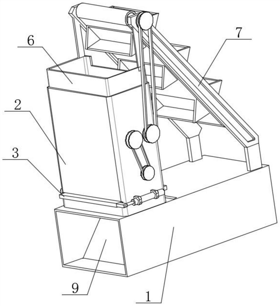
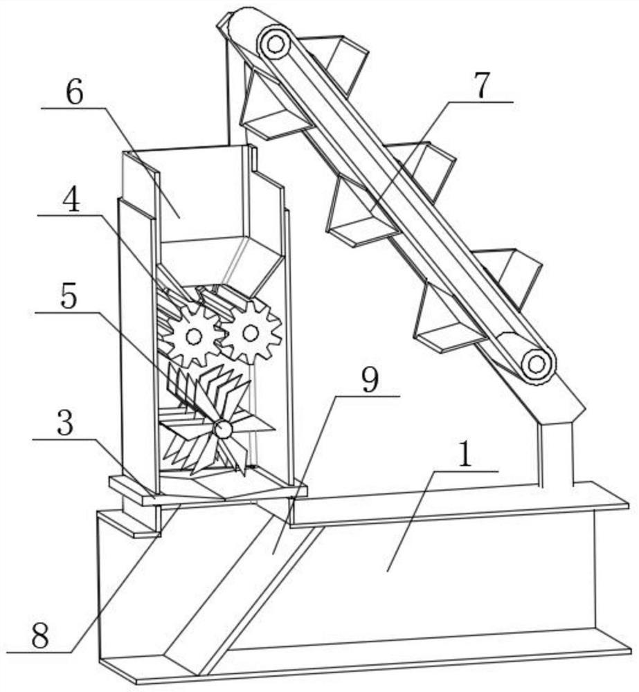
[0033] combine Figure 1-7 As shown, the invention provides a special high-efficiency treatment equipment for ship door production waste, including: a fixed box 1, a treatment box 2 is arranged on the top of the fixed box 1, and a sealing mechanism 3 is arranged inside the treatment box 2 , the inside of the processing box 2 is provided with a crushing mechanism 4 and a crushing mechanism 5, the crushing mechanism 4 is connected with the crushing mechanism 5, the crushing mechanism 5 is located under the crushing mechanism 4, and the crushing mechanism 5 is located at the sealing mechanism 3 above, the crushing mechanism 4 is used to crush the waste, the sealing mechanism 3 is used to block the waste, the shredding mechanism 5 is used to cut the waste, and the top of the processing box 2 is connected with a conical feed hopper 6, The bottom of the conical feed hopper 6 extends to the inside of the processing box 2, the conical feed hopper 6 is located above the crushing mechan...

Embodiment 2

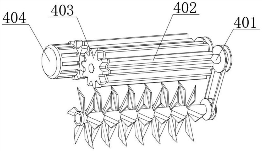
[0036] combine Figure 2-4As shown, on the basis of Embodiment 1, the crushing mechanism 4 includes two first rotating rods 401 and two crushing long rollers 402, and the two first rotating rods 401 are rotatably connected to the inside of the processing box 2, One ends of the two first rotating rods 401 all extend out of the treatment box 2, and the two long crushing rollers 402 are sleeved on the circumferential surfaces of the two first rotating rods 401 respectively, and the outer surfaces of the two long crushing rollers 402 The surfaces mesh with each other, and the two crushing long rollers 402 are located inside the processing box 2. The crushing mechanism 4 also includes two gears 403 and a driving motor 404, and the two gears 403 are respectively sleeved in the two first rotating The circumferential surface of the rod 401 and the outer surfaces of the two gears 403 are engaged with each other. The driving motor 404 is arranged on the rear end face of the processing b...

Embodiment 3

[0039] to combine Figure 5 As shown, in the above embodiment, the sealing mechanism 3 includes two installation bars 301, two sealing plates 302 and two oblique material retaining grooves 303, and the two installation bars 301 are connected to the inner wall of the processing box 2 respectively. On the front end face and the rear end face, the adjacent sides of the two installation bars 301 are provided with chute, and the two sealing plates 302 are slidingly connected between the inner walls of the two chute respectively, and the adjacent sides of the two sealing plates 302 are connected to each other. contact, the opposite sides of the two sealing plates 302 extend out of the processing box 2, and the two oblique material retaining grooves 303 are set on the tops of the two sealing plates 302 respectively, and the sealing mechanism 3 also includes two electric push rods 304, four fixed mounts 305 and two connecting fixed blocks 306, the four fixed mounts 305 are respectivel...


PUM


Abstract

The invention discloses special efficient treatment equipment for ship door production waste, which comprises a fixed box body, the top of the fixed box body is provided with a treatment box body, the treatment box body is internally provided with a sealing mechanism, the treatment box body is internally provided with a grinding mechanism and a chopping mechanism, the grinding mechanism is connected with the chopping mechanism, and the chopping mechanism is connected with the grinding mechanism. The chopping mechanism is located below the crushing mechanism, a driving motor is started to drive a first rotating rod, two first rotating rods and two long crushing rollers rotate in different directions through meshing of two gears, waste is crushed through meshing of the two long crushing rollers, and the crushing efficiency is improved. One first rotating rod can drive one first transmission wheel to transmit a first transmission chain, the first transmission chain drives a second rotating rod to rotate through the other first transmission wheel, the second rotating rod cuts up waste again through multiple sets of cutting blades, and therefore the waste treatment speed is increased, and the waste treatment efficiency is improved.

Description

technical field [0001] The invention relates to the technical field of ship door production, in particular to a special high-efficiency treatment equipment for ship door production waste. Background technique [0002] Ship, the general term for all kinds of ships. A ship is a means of transportation that can sail or berth in waters for transportation or operation. It has different technical performance, equipment and structural types according to different use requirements. A ship is a man-made means of transportation that mainly operates in geographical waters. In addition, civilian ships are generally called ships, military ships are called ships, small ships are called boats or boats, and they are collectively called ships or boats. Existing ships are equipped with special doors. [0003] In the production process of the existing special doors, a large amount of waste chips and blocky waste materials will be generated. These waste materials are difficult to deal with, an...

Claims


Application Information

Patent Timeline
Patent Type & Authority Applications(China)
IPC IPC(8): B02C4/08B02C23/02B02C18/14B02C18/22
Inventor 宋勇荣吴海坝
Owner WUXI DONGZHOU MARINE EQUIP CO LTD
Why Eureka
Try Eureka