SMT template and detection system
A detection system and template technology, applied in metal processing equipment, welding equipment, manufacturing tools, etc., can solve the problems of fatigue of observers, impact on human health, and low detection efficiency of detection equipment, so as to reduce manpower operations and improve detection efficiency Effect
Inactive Publication Date: 2022-04-08
GENERALTEC TIANJIN
View PDF0 Cites 0 Cited by
- Summary
- Abstract
- Description
- Claims
- Application Information
AI Technical Summary
Problems solved by technology
[0003] In the prior art, after each inspection of the precision template, it is necessary to repeatedly lift the upper plate of the inspection box and put in a new precision template, and the observer needs to lower his head and bend over during the inspection, which may easily cause fatigue to the observer. The detection efficiency of precision template detection equipment is not high, which affects human health
Method used
View moreImage
Smart ImageViewing Examples
Examples
Embodiment
[0014] as attached figure 1 Shown:
Login to View More PUM
 Abstract
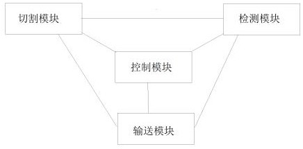
The invention provides an SMT template and detection system, the SMT template and detection system comprises a cutting module, a conveying module, a control module and a detection module, the cutting module internally comprises a laser cutting machine, a cutting head, an annular nozzle and a moving device, the conveying module internally comprises a conveying belt and a mechanical gripper, and the conveying module internally comprises a laser cutting machine, a cutting head, an annular nozzle and a moving device. A linear CCD scanning device is arranged in the detection module, the cutting module is connected with the detection module, the cutting module and the detection module are respectively connected with the conveying module, and the cutting module, the conveying module and the detection module are respectively connected with the control module. According to the SMT template detection device, the control module controls the conveying module to convey the SMT template into the cutting module for cutting, the control module controls the conveying module to convey the cut SMT template into the detection module for detection after cutting, manual operation is not needed in the whole process, manual operation is reduced, and the detection efficiency is improved.
Description
technical field [0001] The invention belongs to the technical field of SMT template processing, and in particular relates to an SMT template and a detection system. Background technique [0002] In the process of SMT template production, when the stainless steel sheet is laser cut, its quality needs to be inspected. At present, it is mainly by placing a light bulb at the bottom of a test box, setting a piece of translucent glass on the upper surface of the test box, placing the tested precision template on the translucent glass, and observing the quality and quality of the tested precision template with the naked eye. After testing a precision template, lift the upper plate of the test box, take out the precision template, and then put another one in for repeated testing. [0003] In the prior art, after each inspection of the precision template, it is necessary to repeatedly lift the upper plate of the inspection box and put in a new precision template, and the observer ne...
Claims
Login to View More Application Information
Patent Timeline
 Patent Type & Authority Applications(China)
IPC IPC(8): B23K26/38B23K26/70
Inventor 刘志新邢海玉梁付全
Owner GENERALTEC TIANJIN
- R&D Engineer
- R&D Manager
- IP Professional
- Industry Leading Data Capabilities
- Powerful AI technology
- Patent DNA Extraction
Learn More Browse by: Latest US Patents, China's latest patents, Technical Efficacy Thesaurus, Application Domain, Technology Topic, Popular Technical Reports.
© 2024 PatSnap. All rights reserved.Legal|Privacy policy|Modern Slavery Act Transparency Statement|Sitemap|About US| Contact US: help@patsnap.com


