Construction auxiliary installation device and construction method thereof

An installation device and hollow technology, which is applied to valve devices, cocks including cut-off devices, transportation and packaging, etc., can solve the problems of inability to install glass curtain walls and inconvenient operation of glass curtain walls, so as to improve convenience, practicability, and security. The effect of reliability

Pending Publication Date: 2022-04-08
浙江经典建筑装饰有限公司
8 Cites 3 Cited by

AI-Extracted Technical Summary

Problems solved by technology

The auxiliary installation device in the above-mentioned patent has the following disadvantages: during construction, it only transports the glass curtain wall to the designated construction p...

Method used

By arranging structures such as connection seat 3, elastic film 32, constitute the floating structure of sucker 10, make it can fit glass curtain wall unit better, when absorbing to glass curtain wall unit, due to the air pressure in hollow frame 1 decrease, the elastic membrane 32 shrinks into the connecting seat 3, and then one end of the connecting pipe 11 extends into the inner side of the connecting seat 3, and when the inner diameter of the connecting seat 3 is the smallest, it is adapted to the diameter of the connecting pipe 11, and finally the connecting seat 3 can be connected The pipe 11 is reliably limited, which improves the stability of the suction cup 10 during adsorption and ensures the reliability of the installation process.
[0086] By setting the...

Abstract

The invention discloses a construction auxiliary installation device and a construction method thereof, and relates to the technical field of glass curtain wall construction. Construction is facilitated; the device comprises a hollow frame; the connecting seats are fixed to the two sides of the hollow frame, and the connecting seats are communicated with the interior of the hollow frame; a connecting pipe is fixed to one end of the suction cup, the connecting pipe is installed in the connecting base, and the suction cup is communicated with the connecting base through the connecting pipe; the method comprises the following steps that a constructor transports a glass curtain wall unit to a designated position; and the suction cups are pressed on the surface of curtain wall glass of the glass curtain wall unit. By arranging the operating rod, the piston, the suction cup and other structures, the suction cup can be attached to the glass curtain wall unit to be installed, the piston is driven to move in the exhaust chamber by repeatedly pulling the operating rod, then gas is exhausted through the exhaust valve, and the suction cup is tightly adsorbed to the glass curtain wall unit; therefore, the glass curtain wall unit can be conveniently lifted and installed, and the practicability is improved.

Application Domain

Plug valvesWalls +3

Technology Topic

PistonMechanical engineering +3

Image

  • Construction auxiliary installation device and construction method thereof
  • Construction auxiliary installation device and construction method thereof
  • Construction auxiliary installation device and construction method thereof

Examples

  • Experimental program(3)

Example Embodiment

[0069] Example 1:
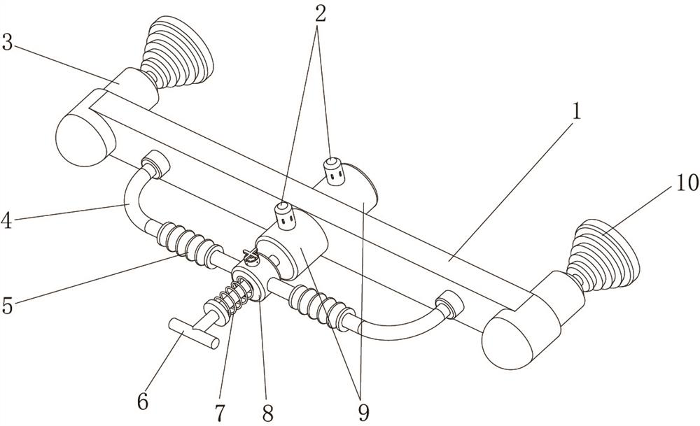
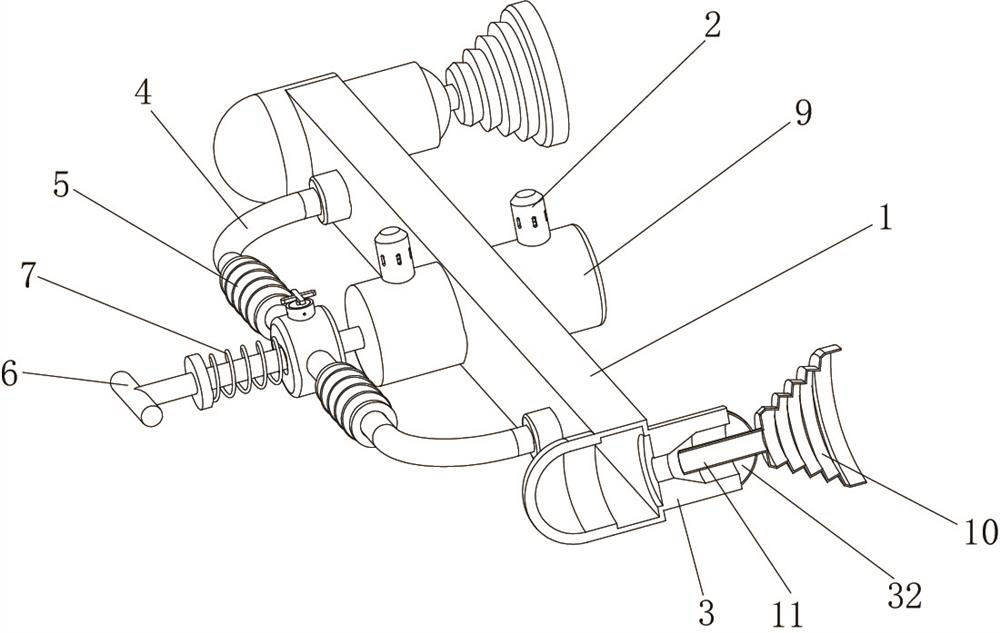
[0070] A construction auxiliary installation device, such as Figure 1-8 shown, including:
[0071] hollow frame 1;
[0072] The connecting seat 3, the connecting seat 3 is fixed on both sides of the hollow frame 1, and the connecting seat 3 is connected with the interior of the hollow frame 1;
[0073] The suction cup 10, one end of the suction cup 10 is fixed with a connecting pipe 11, the connecting pipe 11 is installed in the connecting seat 3, and the suction cup 10 communicates with the connecting seat 3 through the connecting pipe 11;
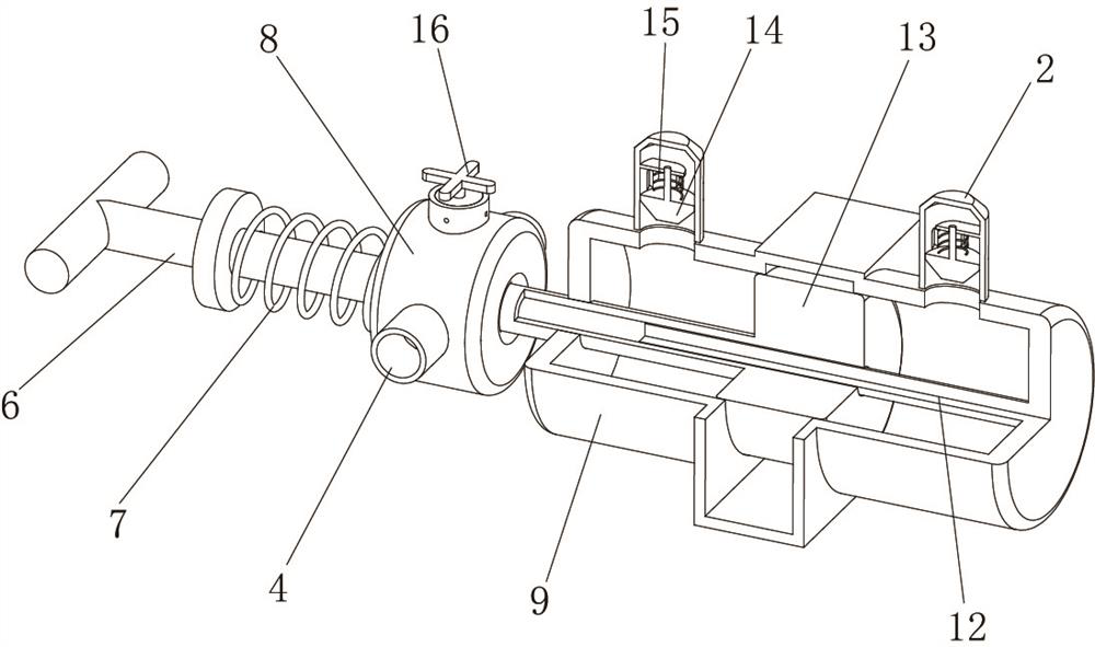
[0074] The exhaust chamber 9 is integrally arranged on both sides of the middle of the hollow frame 1, and an exhaust valve is arranged on the exhaust chamber 9;
[0075] Piston 13, the piston 13 is adapted to the exhaust chamber 9, and the piston 13 is slidably connected in the exhaust chamber 9;
[0076] A guide rod 12, one end of the guide rod 12 is fixed on one side inner wall of an exhaust chamber 9, and the piston 13 is slidably connected to the outer wall of the guide rod 12;
[0077] The operating rod 6, one end of the operating rod 6 is fixed to the outer wall of one side of the piston 13, and the operating rod 6 is sealed and slidably connected to the inner wall of one side of an exhaust chamber 9;
[0078] an air intake assembly, the air intake assembly is communicated in the hollow frame 1, and is used to supplement gas into the hollow frame 1;
[0079] By arranging the operating rod 6, the piston 13 and the suction cup 10 and other structures, the suction cup 10 can be attached to the glass curtain wall unit to be installed. The air valve discharges the gas, so that the suction cup 10 is tightly adsorbed on the glass curtain wall unit, so that the glass curtain wall unit can be easily lifted and installed, and the practicability is improved.
[0080] In order to facilitate adsorption; such as figure 1 , figure 2 As shown in the figure, the inner diameter of the connecting seat 3 gradually decreases in the direction away from the suction cup 10. When the inner diameter of the connecting seat 3 is the smallest, it matches the diameter of the connecting pipe 11. The outer wall of the connecting seat 3 and the connecting pipe 11 are adhered Connected with the same guide rod 12;
[0081] By arranging the connecting seat 3, the elastic film 32 and other structures, the floating structure of the suction cup 10 is formed, so that it can better fit the glass curtain wall unit. The elastic film 32 shrinks into the connecting seat 3, so that one end of the connecting pipe 11 protrudes into the inner side of the connecting seat 3, and the inner diameter of the connecting seat 3 is adapted to the diameter of the connecting pipe 11 when the inner diameter is the smallest. The reliable position limit improves the stability of the suction cup 10 during adsorption, and ensures the reliability of the installation process.
[0082] For ease of operation; such as figure 1 , figure 2 As shown, the air intake assembly includes:
[0083] The holding frame 4, both ends of the holding frame 4 are fixed on the outer wall of one side of the hollow frame 1, and the inside of the holding frame 4 is connected with the inside of the hollow frame 1;
[0084] The annular seat 8 is integrally arranged in the middle of the holding frame 4 , the annular seat 8 is connected to the inside of the holding frame 4 , the operating rod 6 is slidably connected to the inner wall of the annular seat 8 , and the outer wall of one side of the annular seat 8 is fixed between the operating rod 6 have the same first spring 7;
[0085] Intake valve, the intake valve is arranged on the top of the annular seat 8;
[0086] By arranging structures such as the first spring 7, after the operating rod 6 is pulled, the elastic force of the first spring 7 can be used to drive the operating rod 6 to return, which improves the convenience of operation.
[0087] To facilitate venting; such as image 3 , Figure 4 As shown, the exhaust valve includes:
[0088] The valve shell 2, the valve shell 2 is fixed on the outer wall of the top of the exhaust chamber 9;
[0089] The valve plug 14, the valve plug 14 is installed inside the valve housing 2 through the second spring 15, and the valve plug 14 is sealed and slidably connected to the inner wall of the valve housing 2;
[0090] The exhaust hole 17 is opened on the circumferential outer wall of the valve housing 2 , and the exhaust hole 17 is located on the side of the valve plug 14 away from the exhaust chamber 9 .
[0091] In order to facilitate air intake; such as Figure 4 , Figure 5 As shown, the intake valve includes:
[0092] an air intake seat 18, the air intake seat 18 is fixed on the outer wall of the top of the annular seat 8, and a first air intake hole 22 is opened on the circumferential outer wall of the air intake seat 18;
[0093] The sealing slip ring 20 is installed on the inner circumferential wall of the air inlet seat 18;
[0094] The sealing member 19, the sealing member 19 is connected to the inner side of the sealing slip ring 20 in a sealed rotation, and the sealing member 19 is provided with a second air inlet hole 21 adapted to the first air inlet hole 22; the top of the sealing member 19 is integrally provided With knob 16;
[0095] By setting the air inlet valve, the knob knob 16 can be used to align the second air inlet hole 21 with the first air inlet hole 22, so that the inside of the annular seat 8 is connected to the outside world, so that the gas can flow into the annular seat 8, and then It is added to the hollow frame 1 to release the suction of the glass curtain wall unit by the suction cup 10 .
[0096] To improve practicality; such as figure 1 , figure 2 As shown, the outer wall of the holding frame 4 is bonded with a non-slip sleeve 5, and the anti-slip sleeve 5 is provided with an annular finger groove.

Example Embodiment

[0097] Example 2:
[0098] A construction auxiliary installation device, such as Figure 1-8 As shown, in order to facilitate construction; this embodiment makes the following improvements on the basis of Embodiment 1: the specific structure of the glass curtain wall includes:
[0099] The curtain wall frame body 23 is used as the main frame of the building installation glass curtain wall unit;
[0100] The glass curtain wall unit, the glass curtain wall unit includes a curtain wall glass 24 and an installation frame 26, and the curtain wall glass 24 is fixed on the inner side of the installation frame 26;
[0101] The locking part is used to fix the glass curtain wall unit on the curtain wall frame body 23;
[0102] The decorative baffle 25 is clamped on the side of the locking portion away from the curtain wall frame body 23, and plays the role of decoration and protection.
[0103] In order to ensure the locking effect; such as Figure 6-8 As shown, the locking portion includes:
[0104] The slide rail 28, the slide rail 28 is integrally arranged on the outer wall of one side of the curtain wall frame body 23;
[0105] The sliding seat 29, the sliding seat 29 is slidably connected to the inner wall of the sliding rail 28;
[0106] Fastening screws 31, the fastening screws 31 are connected to the inner wall of the sliding seat 29 through threads;
[0107] The clamping plate 27, the clamping plate 27 is rotatably connected to the outer wall of the fastening screw 31, the mounting frame 26 is provided with a locking groove, and the shape of the clamping plate 27 is adapted to the locking groove.
[0108] To improve sealing; such as Figure 6-8 As shown, the outer wall of one side of the curtain wall frame body 23 is bonded with a sealing strip 30 , and the sealing strip 30 is located between the curtain wall frame body 23 and the curtain wall glass 24 .

Example Embodiment

[0109] Example 3:
[0110] A construction method for a construction auxiliary installation device, comprising the following steps:
[0111] S1: The construction personnel transport the glass curtain wall unit to the designated location;
[0112] S2: pressing the suction cup 10 on the surface of the curtain wall glass 24 of the glass curtain wall unit;
[0113] S3: Pull the operating rod 6 repeatedly to discharge the gas in the hollow frame 1 and the suction cup 10 from the exhaust valve to realize the adsorption of the curtain wall glass 24;
[0114] S4: Hold the anti-skid sleeve 5 in hand, and clamp the glass curtain wall unit on the curtain wall frame body 23;
[0115] S5: Twist the knob 16 to make the outside air enter the hollow frame 1, and release the adsorption effect of the suction cup 10 on the glass curtain wall unit;
[0116] S6: Install the adjacent glass curtain wall units according to the above method;
[0117] S7: Rotate the card plate 27 so that both ends of the card plate 27 are turned into the locking grooves of the two installation frames 26;
[0118] S8: Twist the fastening screw 31 to make the clamping plate 27 approach the curtain wall frame body 23, so as to press and lock the installation frame 26;
[0119] S9: Install the decorative baffle 25;
[0120] S10: Repeat the above steps until the construction of the glass curtain wall is completed.

PUM

no PUM

Description & Claims & Application Information

We can also present the details of the Description, Claims and Application information to help users get a comprehensive understanding of the technical details of the patent, such as background art, summary of invention, brief description of drawings, description of embodiments, and other original content. On the other hand, users can also determine the specific scope of protection of the technology through the list of claims; as well as understand the changes in the life cycle of the technology with the presentation of the patent timeline. Login to view more.

Similar technology patents

Television bracket

InactiveCN102691862AEasy to fix the cameraImprove practicality
Owner:SUZHOU QINGDING PRECISION MACHINERY PROD

Environmentally-friendly textile machine with functions of shock absorption and cotton flock absorption

PendingCN107575718AImprove practicalityAvoid excessive vibration
Owner:长兴宝诺纺织科技有限公司

Processing method and equipment of electronic health service

InactiveCN104715128AImprove practicality
Owner:CHINA MOBILE COMM GRP CO LTD

Charging equipment based on internet of things for charging of new energy automobile

InactiveCN107554337AImprove practicalityAchieve stable output
Owner:NANJING WEILI INNOVATIVE ENERGY TECH CO LTD

Classification and recommendation of technical efficacy words

  • Improve stability
  • Improve practicality
Why Eureka
Try Eureka