Sleeve detection equipment based on image recognition
A technology for image recognition and detection equipment, which is applied in the direction of measuring devices, material analysis through optical means, instruments, etc., can solve the problems of high labor intensity, prone to missed detection and false detection, and low degree of automation, so as to reduce the risk of interference, Reduce the effect of missed detection
- Summary
- Abstract
- Description
- Claims
- Application Information
AI Technical Summary
Problems solved by technology
Method used
Image

Examples
Embodiment 1
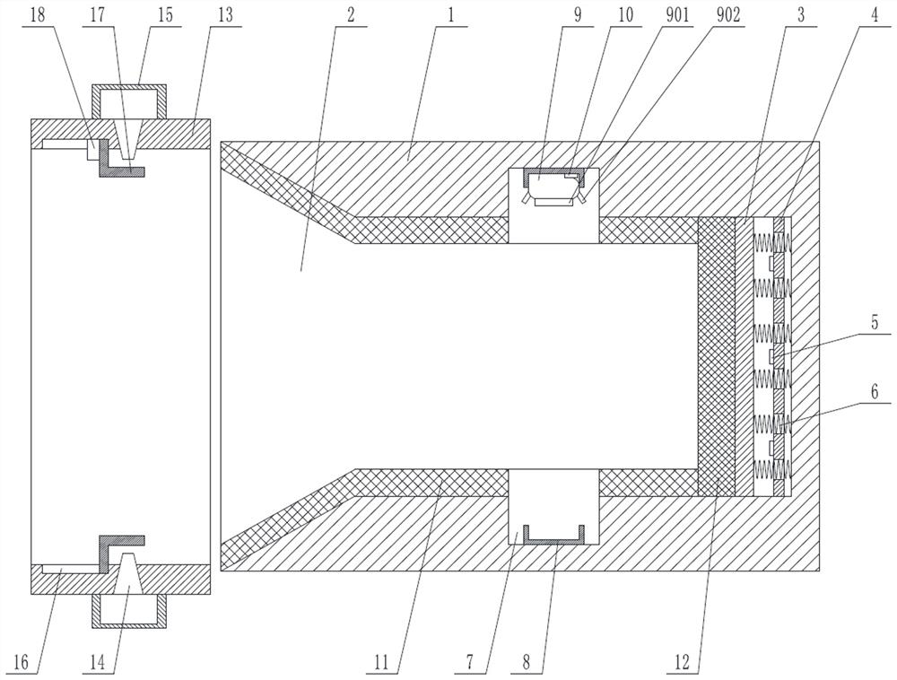
[0039] Such as figure 1 The shown bushing detection equipment based on image recognition includes a box body 1, a groove 2 opened on the side of the box body 1, a flat plate 3 slidingly fitted with the inner wall of the groove 2, and a positioning plate 4 fixedly connected with the inner wall of the groove 2 , the positioning plate 4 is parallel to the flat plate 3, and the positioning plate 4 is located between the flat plate 3 and the groove bottom of the groove 2; it also includes a touch sensing device 5 arranged on the surface of the positioning plate 4, which moves through The elastic buffer 6 of the positioning plate 4, the touch sensing device 5 is located on the side surface of the positioning plate 4 facing the direction of the flat plate 3, and the opposite ends of the elastic buffer 6 are connected to the flat plate 3 and the groove 2 respectively. The bottom of the tank is connected;
[0040] It also includes a first annular groove 7 set on the groove wall of the...
Embodiment 2
[0048] On the basis of embodiment 1, the casing inspection equipment based on image recognition also includes a heating tube 13 located outside the notch of the groove 2, the heating tube 13 is coaxial with the groove 2, and the inner wall of the heating tube 13 is set Several steam nozzles 14 also include a gas collection box 15 fixed outside the heating pipe 13, and the gas collection box 15 is used to communicate with the steam generating device; all steam nozzles 14 are in communication with the gas collection box 15.
[0049] It also includes a second annular groove 16 on the inner wall of the heating tube 13, an annular stopper 17 slidingly fitted in the second annular groove 16, and is used to drive the annular stopper 17 to move axially along the second annular groove 16. The second driving device 18;
[0050] The annular stopper 17 has a shielding station and a heating station in the second annular groove 16, and the second driving device 18 drives the annular stopper...
Embodiment 3
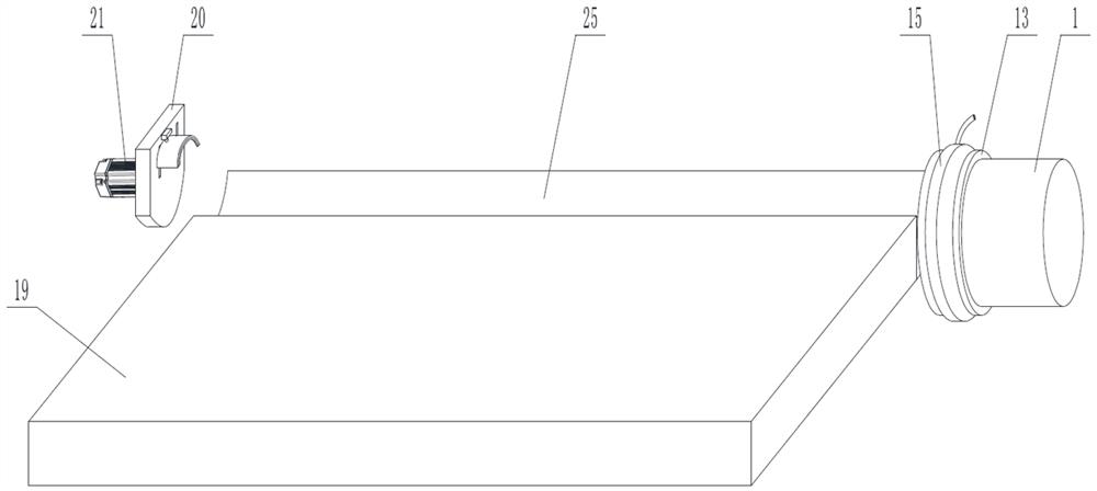
[0057] A kind of bushing detection equipment based on embodiment 2, such as figure 2 As shown, it also includes a single groove 25 located at the end of the heating tube 13 away from the direction of the box body 1. The bottom of the single groove 25 is arc-shaped and is used to accommodate a single sleeve. The tubes 13 are coaxial; and a discharge platform 19 adjacent to the single groove 25 is also included.
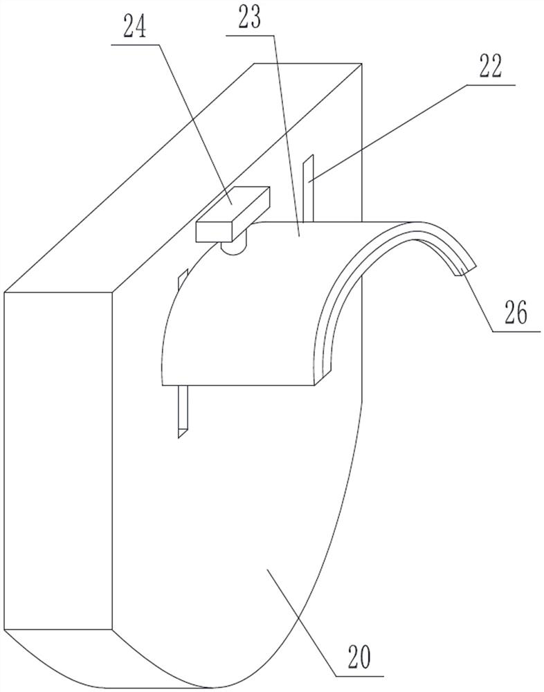
[0058] Such as figure 2 and image 3 As shown, it also includes a push plate 20 located at the end of the single groove 25 away from the direction where the heating tube 13 is located, and a third driving device 21 for driving the push plate 20 to make a linear reciprocating motion along the axis of the single groove 25 . The side surface of the push plate 20 facing the direction of the heating tube 13 is provided with a longitudinally distributed slide rail 22, an arc-shaped hook plate 23 slidingly fitted on the slide rail 22, and is used to drive the arc-shaped hoo...
PUM
 Abstract
Description
Claims
Application Information
 - R&D
- Intellectual Property
- Life Sciences
- Materials
- Tech Scout
- Unparalleled Data Quality
- Higher Quality Content
- 60% Fewer Hallucinations
Browse by: Latest US Patents, China's latest patents, Technical Efficacy Thesaurus, Application Domain, Technology Topic, Popular Technical Reports.
© 2025 PatSnap. All rights reserved.Legal|Privacy policy|Modern Slavery Act Transparency Statement|Sitemap|About US| Contact US: help@patsnap.com