Low small obstacle detection method and device based on three cameras, and terminal equipment
An obstacle detection and camera technology, applied in the field of automatic driving visual perception, to achieve the effect of enhancing perception ability
- Summary
- Abstract
- Description
- Claims
- Application Information
AI Technical Summary
Problems solved by technology
Method used
Image

Examples
Embodiment 1
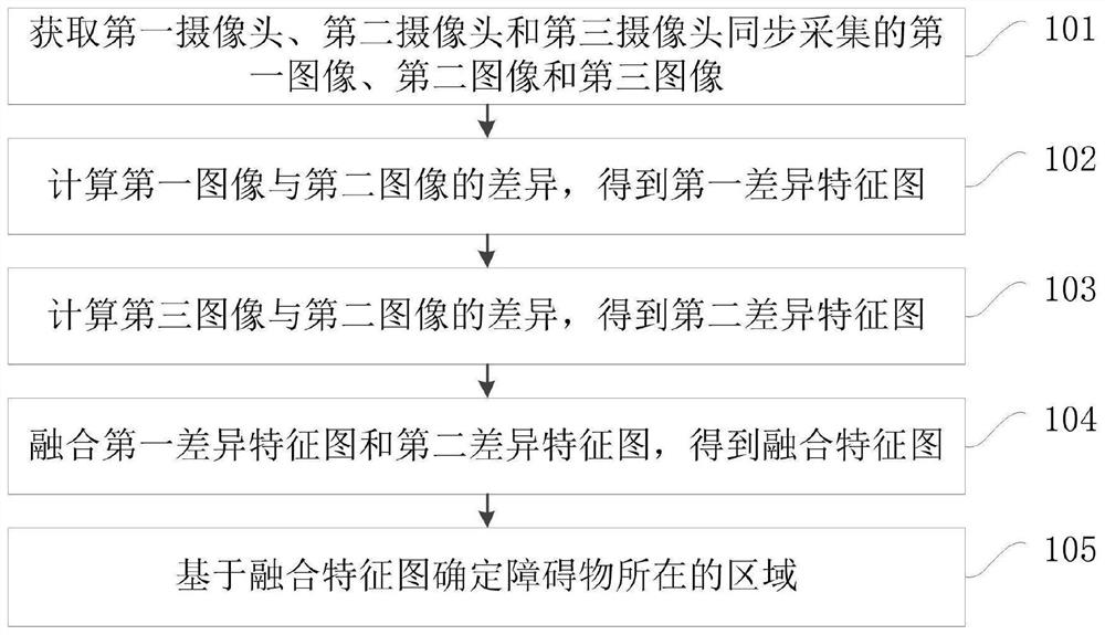
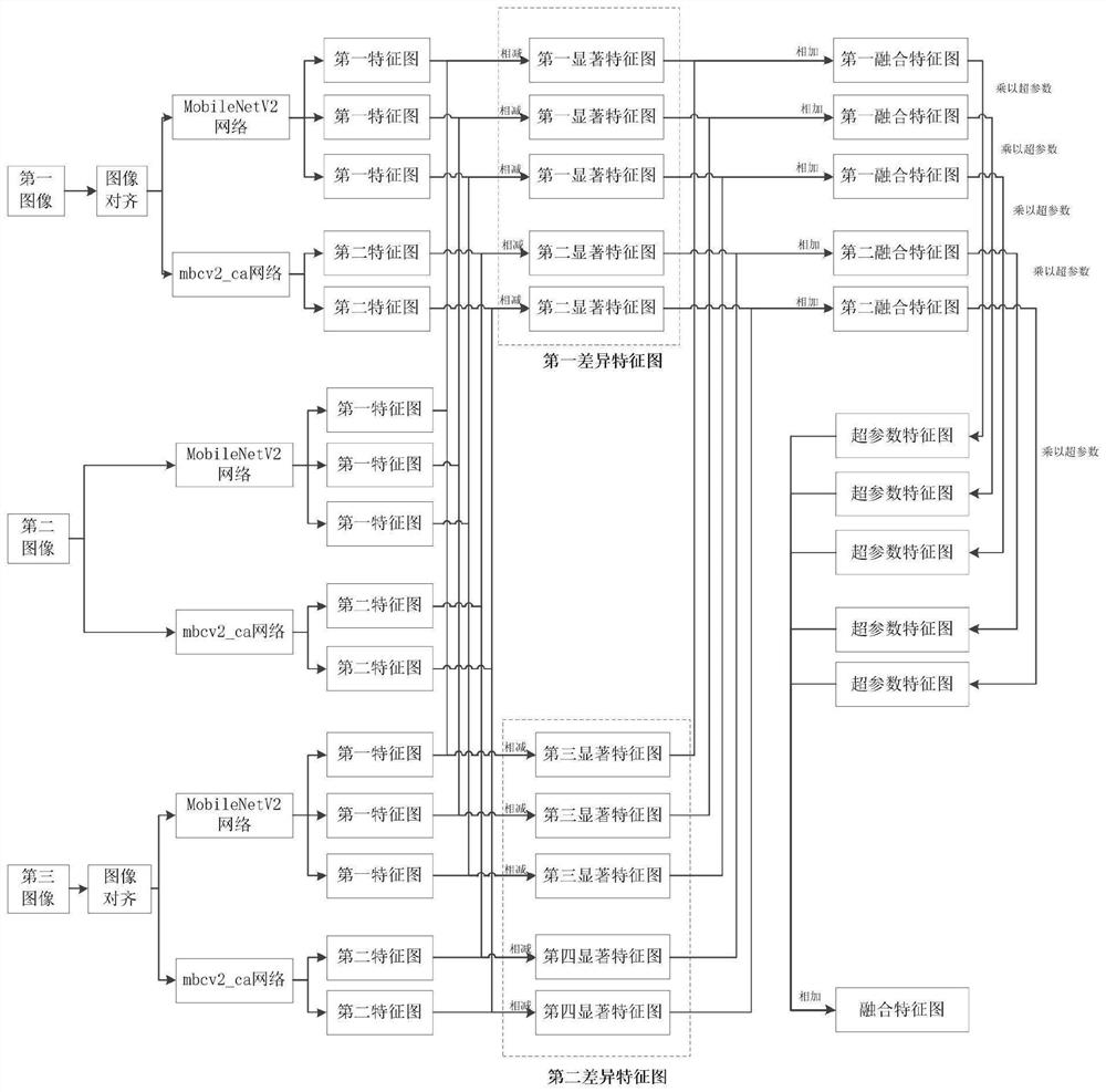
[0035] Figure 1A It is a flow chart of a three-camera-based low-short obstacle detection method provided by Embodiment 1 of the present invention, Figure 1B It is an example flow chart of data processing of the method for detecting low and small obstacles based on three cameras in Embodiment 1 of the present invention. This embodiment is applicable to improving the detection accuracy of low and small obstacles. The low and small obstacle detection device based on three cameras can be implemented by software and / or hardware, and can be configured in computer equipment, robots, for example, intelligent robots, servers, personal computers , etc., specifically include the following steps:
[0036] Step 101. Obtain a first image, a second image, and a third image that are synchronously captured by the first camera, the second camera, and the third camera.
[0037] Exemplarily, the first camera, the second camera, and the third camera are all set on the same plane, and are all us...
Embodiment 2
[0140] figure 2 The structural block diagram of a low and short obstacle detection device provided in Embodiment 2 of the present invention may specifically include the following modules:
[0141] An image acquisition module 201, configured to acquire a first image, a second image, and a third image synchronously acquired by the first camera, the second camera, and the third camera;
[0142] A first difference feature calculation module 202, configured to calculate the difference between the first image and the second image to obtain a first difference feature map;
[0143] The second difference feature calculation module 203, configured to calculate the difference between the third image and the second image to obtain a second difference feature map;
[0144] A difference fusion module 204, configured to fuse the first difference feature map and the second difference feature map to obtain a fusion feature map;
[0145] The post-processing module 205 is configured to determ...
Embodiment 3
[0172] image 3 It is a schematic structural diagram of a low and short obstacle detection device provided by Embodiment 3 of the present invention. image 3 A block diagram of an exemplary low obstacle detection device 12 suitable for implementing embodiments of the present invention is shown. image 3 The low and small obstacle detection device 12 shown is only an example, and should not impose any limitation on the function and application scope of the embodiment of the present invention.
[0173] Such as image 3 As shown, the low obstacle detection device 12 is represented in the form of a general-purpose computing device. Components of the low obstacle detection device 12 may include, but are not limited to: one or more processors or processing units 16 , a system memory 28 , and a bus 18 connecting different system components (including the system memory 28 and the processing unit 16 ).
[0174] Bus 18 represents one or more of several types of bus structures, includ...
PUM
 Abstract
Description
Claims
Application Information
 - R&D
- Intellectual Property
- Life Sciences
- Materials
- Tech Scout
- Unparalleled Data Quality
- Higher Quality Content
- 60% Fewer Hallucinations
Browse by: Latest US Patents, China's latest patents, Technical Efficacy Thesaurus, Application Domain, Technology Topic, Popular Technical Reports.
© 2025 PatSnap. All rights reserved.Legal|Privacy policy|Modern Slavery Act Transparency Statement|Sitemap|About US| Contact US: help@patsnap.com