Lighting device

A technology for lighting devices and lighting components, applied to lighting devices, components of lighting devices, lighting and heating equipment, etc., can solve problems such as false detection and increased complexity, and achieve the effect of reducing complexity

Pending Publication Date: 2022-04-08
LUMILEDS HLDG BV
View PDF2 Cites 0 Cited by
  • Summary
  • Abstract
  • Description
  • Claims
  • Application Information

AI Technical Summary

Problems solved by technology

Further, error detection is often required in the automotive field and needs t...

Method used


Image

  • Lighting device
  • Lighting device
  • Lighting device

Examples


Embodiment Construction

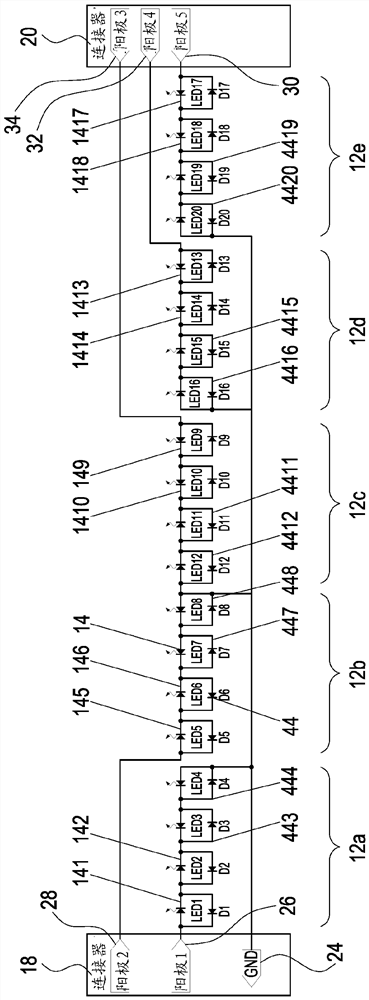
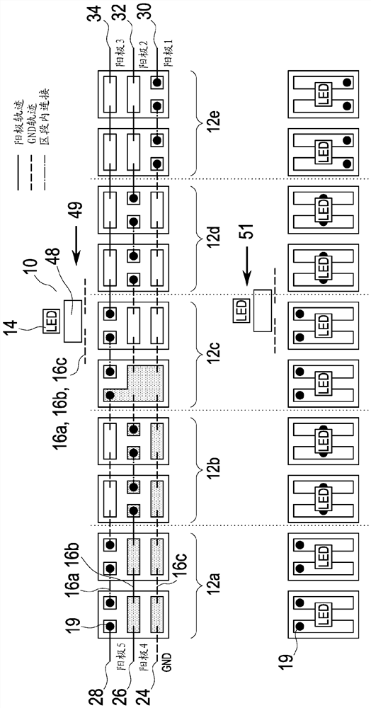
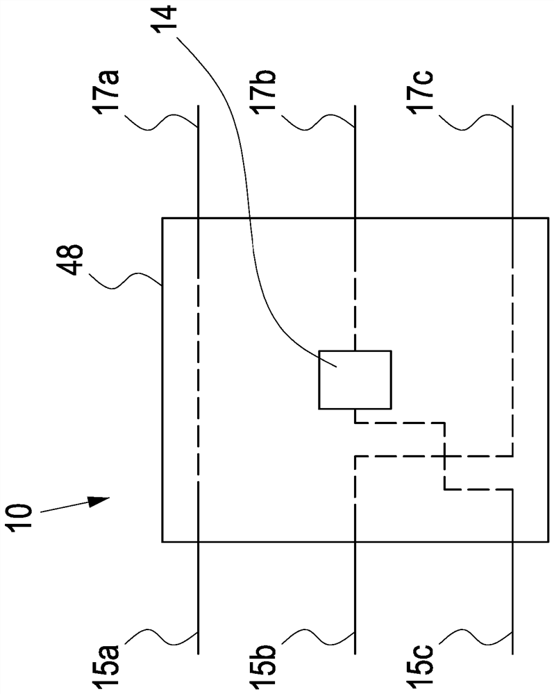
[0056] In the following description, for purposes of explanation and not limitation, specific details are set forth, such as specific architectures, interfaces, techniques, etc., in order to provide a thorough understanding of the concepts of the present invention. It will be apparent, however, to one skilled in the art that the present invention may be practiced in other embodiments that depart from these specific details. In like manner, the text of this description is directed to the example embodiments as illustrated in the figures, and is not intended to limit the claimed invention beyond the limits expressly included in the claims. For purposes of brevity and clarity, detailed descriptions of well-known devices, circuits, and methods are omitted so as not to obscure the description of the present invention with unnecessary detail. The following description should not be read as limiting the assignment of any specific feature to a specific embodiment. Therefore, the feat...


PUM


Abstract

A lighting device, in particular for motor vehicle lighting applications, comprises a plurality of lighting elements arranged in one or more rows so as to form a light strip, where each lighting element comprises at least one or more light emitting diodes (LEDs). The plurality of lighting elements is divided into one or more sections, wherein the lighting elements within each section are electrically connected in series or in parallel. The lighting device also includes at least one contact element providing current to the plurality of lighting elements, where at least a first contact element provides current to the first set of segments such that the sets of lighting elements are independently and dynamically controlled.

Description

technical field [0001] The present invention relates to a lighting device, particularly for automotive lighting applications, and more particularly in the form of a lighting strip or lighting strip. Background technique [0002] In the field of motor vehicles, it is currently a trend to implement lighting devices that can be dynamically controlled. This means that it is no longer sufficient that the lighting device can be switched on and off, but in addition the components of the lighting device must be individually adjustable. For example, various components can be turned on and off or dimmed in order to generate dynamic lighting effects. The availability of light-emitting semiconductors (LEDs) has greatly enhanced the development of light-emitting devices that can be dynamically controlled. [0003] The LEDs can be individually controlled by addressing each LED by separate electrical leads. However, this results in the need for numerous wires to be connected to the ligh...

Claims


Application Information

Patent Timeline
IPC IPC(8): F21S4/24F21V23/00F21V23/06H05B45/46H05B45/48H05B47/155F21Y115/10F21W107/10
CPCH05B45/48H05B44/00H05B45/46H05B47/155F21V23/006F21V23/06F21S4/24
Inventor M·格拉弗C·克莱宁U·克拉波夫斯基
Owner LUMILEDS HLDG BV
Why Eureka
Try Eureka