
Automatic fish feed feeding mechanism

An automatic, fish feed technology, applied in fish farming, application, climate change adaptation, etc., can solve the problems of inability to feed, blow away fish feed, and increase the loss rate of fish feed, so as to avoid excessive feeding speed. , the effect of reducing the service life and increasing the cost of feeding

Inactive Publication Date: 2022-04-12
赵利刚
View PDF0 Cites 0 Cited by
  • Summary
  • Abstract
  • Description
  • Claims
  • Application Information

AI Technical Summary

Problems solved by technology

[0002] The bait feeder is a mechanical device for timing and quantitative feeding of aquaculture objects. At present, many kinds of bait feeders are popular. It can be timed, quantitative, and positioned, and has the advantages of saving time and labor. However, using mechanical feeding in When encountering a strong river wind, it is easy to blow away the fish feed, and it is impossible to feed it in the designated area. It is difficult to grasp the feeding direction of the fish feed, which increases the loss rate of the fish feed;
[0003] In addition, the size of fish feed eaten by different fish is different. Some fish are not easy to digest fish feed with large particle size, which may easily cause indigestion.

Method used


Image

  • Automatic fish feed feeding mechanism
  • Automatic fish feed feeding mechanism
  • Automatic fish feed feeding mechanism

Examples


Embodiment Construction

[0022] The following will clearly and completely describe the technical solutions in the embodiments of the present invention with reference to the accompanying drawings in the embodiments of the present invention. Obviously, the described embodiments are only some, not all, embodiments of the present invention. Based on the embodiments of the present invention, all other embodiments obtained by persons of ordinary skill in the art without making creative efforts belong to the protection scope of the present invention.

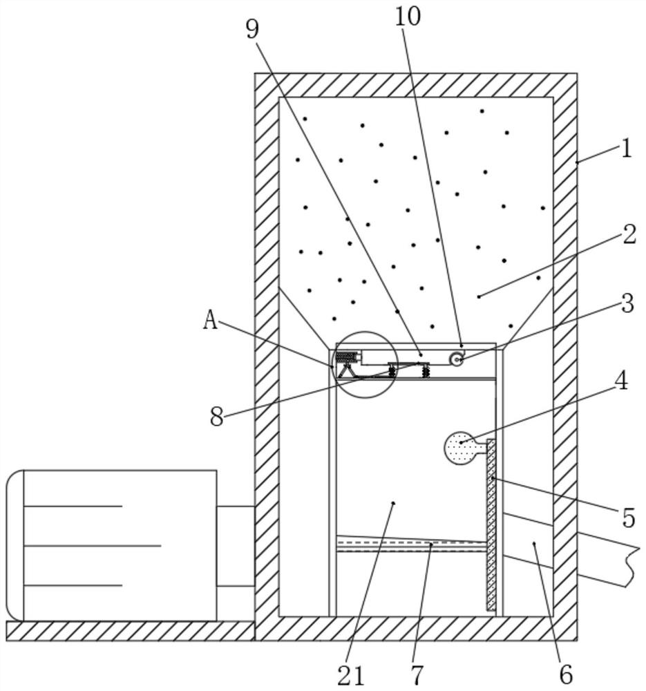
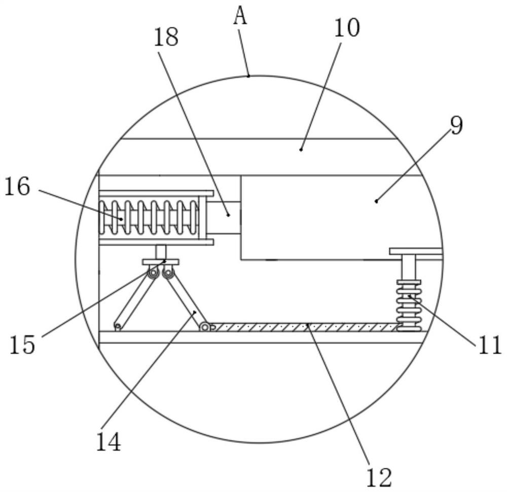
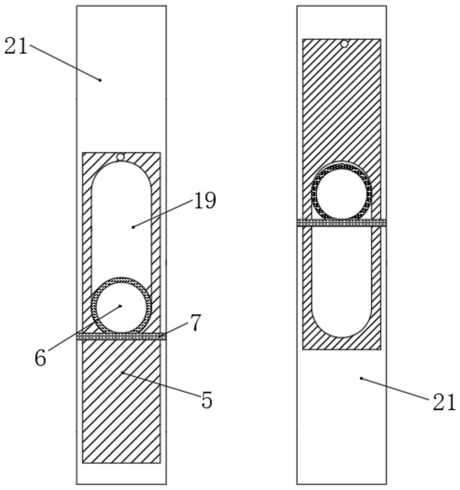
[0023] Please refer to Figure 1-Figure 6 , an automatic feeding mechanism for fish feed, comprising a box body 1 and a storage box 2 provided above the inside of the box body 1, the bottom of the storage box 2 is connected with a lower material box 21, and the top of the lower material box 21 is slidingly installed with a lower material Plate II 10, a chute 19 is opened on one side of the lower material box 21, the inner wall of the lower material box 21 is s...


PUM


Abstract

The invention relates to the technical field of fish feed feeding, and discloses an automatic fish feed feeding mechanism which comprises a box body and a feed storage box arranged on the upper portion of the interior of the box body, the bottom of the feed storage box communicates with a discharging box, a discharging plate II is slidably installed on the top of the discharging box, a sliding groove is formed in one side of the discharging box, and a sliding plate is slidably connected to the inner wall of the discharging box. A sliding plate slides up and down on a discharging box to control the foodstuff size of fishes and eat the fishes with small particle sizes, a discharging barrel can be moved downwards, then a discharging plate I expands through a spring I to move rightwards, the space of a material leaking opening is reduced, the fishes with the small particle sizes can be conveniently fed, and the problems that the discharging speed is too high, feeding is too much, and the fishes cannot eat the foodstuff to be deposited at the water bottom can be avoided; and when small-particle fish feed is fed, the distance between the discharging barrel and the water surface is reduced, so that the situation that the fish feed is wasted and the feeding cost of the fish feed is increased due to the fact that the wind on the river surface is large and most of the fish feed is blown to the unspecified direction can be avoided.

Description

technical field [0001] The invention relates to the technical field of fish feed feeding, in particular to an automatic fish feed feeding mechanism. Background technique [0002] The bait feeder is a mechanical device for timing and quantitative feeding of aquaculture objects. There are many kinds of bait feeders that are popular at present. It can be timed, quantitative, and positioned, and has the advantages of saving time and labor. However, using mechanical feeding When encountering a strong river wind, it is easy to blow away the fish feed, and it is impossible to feed it in the designated area. It is difficult to grasp the feeding direction of the fish feed, which increases the loss rate of the fish feed; [0003] And the size of the fish feed eaten by different fish is different, and some fish are not easy to digest the fish feed with large particle size, which is easy to cause indigestion. Contents of the invention [0004] Aiming at the deficiency of the above-me...

Claims


Application Information

Patent Timeline
Patent Type & Authority Applications(China)
IPC IPC(8): A01K61/80
CPCY02A40/81
Inventor 赵利刚
Owner 赵利刚
Learn More