
Balloon tip wrapping type catheter

A catheter and balloon technology, applied in the field of catheters, can solve problems such as blockage of drainage holes and lack of attention, and achieve the effects of preventing edema, reducing complications and discomfort, and improving quality of life.

Pending Publication Date: 2022-04-12
钱庆鹏
View PDF0 Cites 0 Cited by
  • Summary
  • Abstract
  • Description
  • Claims
  • Application Information

AI Technical Summary

Problems solved by technology

In addition, the protruding and slender apex is easily wrapped by the collapsed bladder wall, causing blockage of the drainage holes near the head
The above-mentioned disadvantages have existed for a long time and have not attracted enough attention. The protruding cusp structure of existing urinary catheters is habitually regarded as an inherent model. At present, no urinary catheter has a structural design that wraps the spire

Method used


Image

  • Balloon tip wrapping type catheter
  • Balloon tip wrapping type catheter

Examples


Embodiment 1

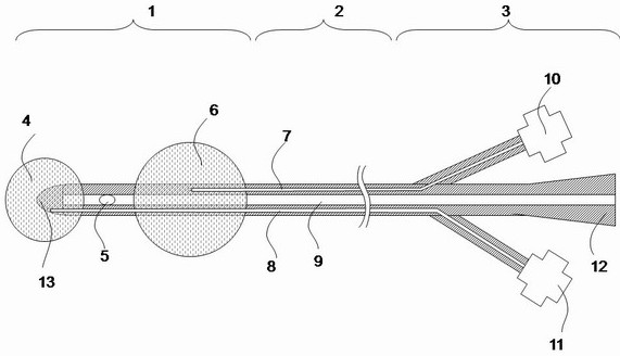
[0010] Embodiment 1: as figure 1 As shown, a urinary catheter with a protective balloon includes a head (1), a body (2), and a tail (3). The head (1) is distributed with a protective balloon (4) and drainage holes (5 ) and a fixed balloon (6), wherein the protective balloon (4) is located outside the tip (13) at the end of the catheter head (1), and the body (2) has a fixed balloon water injection cavity (7), Protective balloon water injection chamber (8) and drainage chamber (9), fixed balloon water injection valve (10), protective balloon water injection valve (11), urine bag interface (12), head (1) at the tail (3) The drainage hole (5) opens to the urine bag interface (12) of the tail (3) through the drainage cavity (9) of the body (2), and the fixed balloon (6) of the head (1) passes through the body (2) The fixed balloon water injection cavity (7) opens to the fixed balloon water injection valve (10) at the tail (3), and the protective balloon (4) of the head (1) passes...

Embodiment 2

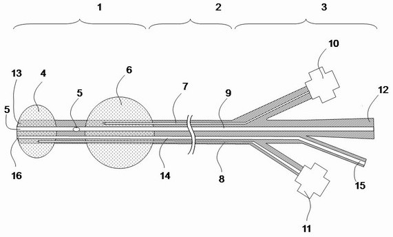
[0011] Embodiment 2: as figure 2 As shown, a urinary catheter with a protective balloon includes a head (1), a body (2), and a tail (3). The head (1) is distributed with a protective balloon (4) and drainage holes (5 ) and a fixed balloon (6), the protective balloon (4) is located outside the tip (13) at the end of the catheter head (1), and the body (2) has a fixed balloon water injection chamber (7), Protective balloon water injection chamber (8), drainage chamber (9) and flushing chamber (14), fixed balloon water injection valve (10), protective balloon water injection valve (11), urine bag interface (12) at the tail (3) 1. The flushing interface (15), the drainage hole (5) of the head (1) opens to the urine bag interface (12) of the tail (3) through the drainage cavity (9) of the body (2), and the drainage hole (5) of the head (1) The fixed balloon (6) opens to the fixed balloon water injection valve (10) at the tail (3) through the fixed balloon water injection chamber ...


PUM


Abstract

The invention relates to a medical instrument, in particular to a catheter with a protective balloon at the tail end of the head. The technical problem to be solved is to overcome the defects of the background technology, an elastic protective balloon is arranged outside a protruding pinnacle part at the tail end of a ureter, the pinnacle part of the ureter is completely wrapped in the protective balloon, damage of the pinnacle at the tail end of the ureter to the bladder wall can be avoided, and the protective effect is achieved. The catheter comprises a head part, a body part and a tail part, the head part is provided with a drainage hole and a fixed balloon, the fixed balloon is opened at a fixed balloon water injection valve at the tail part through a fixed balloon water injection cavity of the body part, and the drainage hole is opened at a urine bag interface at the tail part through a drainage cavity of the body part. The protective balloon is communicated with the protective balloon water injection cavity at the body part and the protective balloon water injection valve at the tail part, the protective balloon can be expanded through water injection or air inflation, and the expanded protective balloon wraps the tip at the tail end of the head part of the catheter in the protective balloon.

Description

technical field [0001] The invention relates to a medical device, in particular to a urinary catheter with a protective balloon at the end of the head. Background technique [0002] A urinary catheter is a medical device used in medicine to drain urine. The most commonly used urinary catheter is the balloon catheter. The function of the balloon of the current urinary catheter is fixation. Specifically, the head of the urinary catheter has an inflatable elastic balloon. The natural state of the balloon is contracted. Inflated like a balloon, the inflated balloon is stuck in the bladder and plays a role in fixing the urinary catheter to prevent prolapse. The current balloon catheter has a pointed protrusion at the end before the balloon. Regardless of whether the fixed balloon is inflated or emptied, the pointed protrusion always protrudes outside the balloon, and this structure has become an inherent mode. In clinical application, the spire will compress the inner wall of ...

Claims


Application Information

Patent Timeline
IPC IPC(8): A61M25/10
Inventor 钱庆鹏
Owner 钱庆鹏
Features
  • Generate Ideas
  • Intellectual Property
  • Life Sciences
  • Materials
  • Tech Scout
  • Unparalleled Data Quality
  • Higher Quality Content
  • 60% Fewer Hallucinations
Learn More