
EGR cooler digital core automatic assembling machine and main control system thereof

A technology of EGR cooler and assembly machine, which is applied in the direction of metal processing equipment, metal processing, manufacturing tools, etc., can solve the problems of automatic compression assembly of inconvenient devices, automatic mechanical clamping of inconvenient devices, and automatic transmission of inconvenient materials, so as to achieve easy operation , the effect of high degree of automation

Pending Publication Date: 2022-04-12
ZHEJIANG YINLUN INTELLIGENT EQUIP CO LTD
View PDF6 Cites 0 Cited by
  • Summary
  • Abstract
  • Description
  • Claims
  • Application Information

AI Technical Summary

Problems solved by technology

[0005] In order to make up for the deficiencies of the existing technology, it solves the problems that it is not convenient to carry out automatic transmission of materials, it is not convenient to carry out automatic mechanical clamping on the device, and it is not convenient to carry out automatic compression assembly on the device

Method used


Image

  • EGR cooler digital core automatic assembling machine and main control system thereof
  • EGR cooler digital core automatic assembling machine and main control system thereof
  • EGR cooler digital core automatic assembling machine and main control system thereof

Examples


Embodiment 1

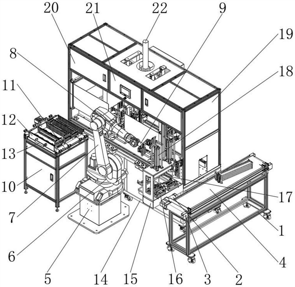
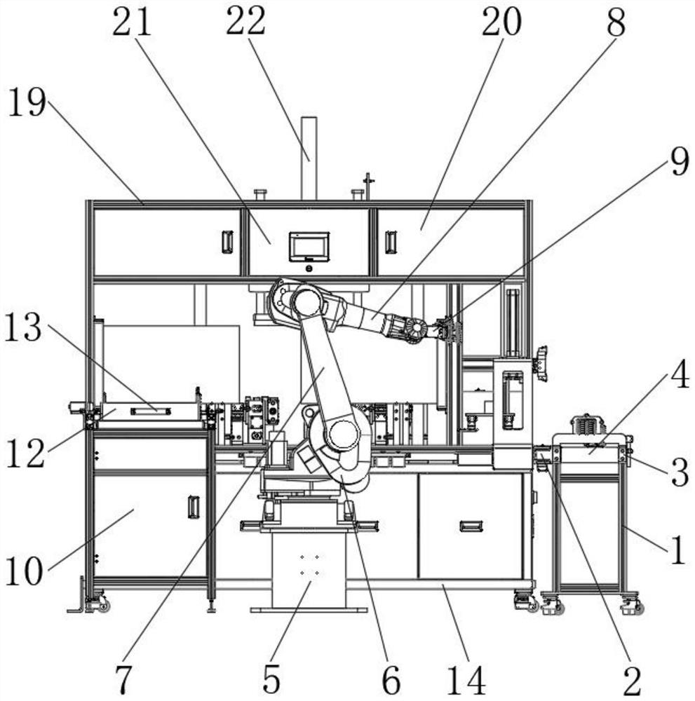
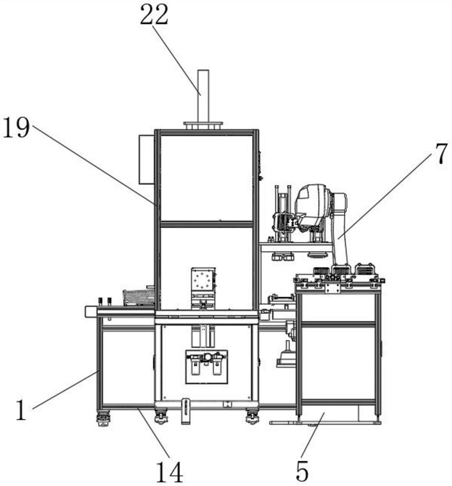
[0033] see Figure 1-4 As shown, the EGR cooler digital core automatic assembly machine includes a conveying frame 1 and a bottom box 14, a servo motor 2 is installed at the end of the conveying frame 1, and a roller head 3 is installed at the end of the servo motor 2, and the roller The outside of the gear head 3 is provided with a transmission belt 4, the side of the conveyor frame 1 is provided with a fixed seat 5, and the top of the fixed seat 5 is provided with a movable frame 6, and the top of the movable frame 6 is connected with a first mechanical arm 7, and the second The end of a mechanical arm 7 is connected with the second mechanical arm 8, and the end of the second mechanical arm 8 is equipped with a connecting gripper 9, the side of the fixed base 5 is provided with a placement cabinet 10, and the top of the placement cabinet 10 is provided with There is a sliding frame 11 , a storage drawer 12 is provided on the inner side of the sliding frame 11 , and a handle ...

Embodiment 2

[0038] see Figure 1-5 As shown in Comparative Example 1, as another embodiment of the present invention, the bottom box 14 is arranged on the side of the storage cabinet 10, and the inside of the bottom box 14 is provided with a processing frame 15, and the inside of the processing frame 15 is provided with a placement seat 16 , and the top of the placement seat 16 is provided with a lower pressing plate 17, and the end of the lower pressing plate 17 is equipped with a telescopic cylinder 18, the top of the bottom box 14 is provided with a main frame 19, and the side of the main frame 19 is provided with a movable drawer 20, The side of movable drawer 20 is provided with maintenance plate 21, and the inner side of maintenance plate 21 is provided with elevator 22, and the end of elevator 22 is provided with circular protective cover 23, and the bottom of circular protective cover 23 is provided with core assembly pressing plate 24. A guide post 25 is provided on the side of t...


PUM


Abstract

The invention belongs to the field of automatic assembling machines, and particularly relates to an EGR cooler digital core automatic assembling machine which comprises a conveying frame and a bottom box, a servo motor is installed at the end of the conveying frame, a roller blocking head is installed at the end of the servo motor, a conveying belt is arranged on the outer side of the roller blocking head, a fixing base is arranged on the side of the conveying frame, and a clamping groove is formed in the bottom box. A movable frame is arranged at the top of the fixed seat, a first mechanical arm is connected to the top of the movable frame, a second mechanical arm is connected to the end of the first mechanical arm, a connecting clamp is mounted at the end of the second mechanical arm, a placement cabinet is arranged on the side of the fixed seat, and a sliding frame is arranged at the top of the placement cabinet. A storage drawer is arranged on the inner side of the sliding frame, a handle is arranged on the outer wall of the storage drawer, and the bottom box is arranged on the side of the containing cabinet. According to the device, automatic conveying of materials is facilitated, automatic mechanical clamping of the device is facilitated, and automatic compression assembling of the device is facilitated.

Description

technical field [0001] The invention relates to the field of automatic assembly machines, in particular to an automatic assembly machine for digitized cores of EGR coolers. Background technique [0002] Assembly refers to the combination of several parts of the product through tight fitting, buckle, screw connection, bonding, riveting, welding, etc. to obtain a finished product (semi-finished product) that meets the predetermined dimensional accuracy and function, and is processed manually ( Strictly speaking, it can only be called manual assembly. Assembly that does not require manual handling (touching, sorting, grabbing, moving, placing, etc.) of components can be called automatic assembly, and semi-automatic assembly is in between. [0003] Traditional automatic assembly machines have the problems of inconvenient automatic material transfer, inconvenient automatic mechanical clamping of devices, and inconvenient automatic compression assembly of devices. [0004] There...

Claims


Application Information

Patent Timeline
Patent Type & Authority Applications(China)
IPC IPC(8): B23P19/00
Inventor 项昶斌刘鹏余仲元朱浩张立超齐韵博
Owner ZHEJIANG YINLUN INTELLIGENT EQUIP CO LTD
Learn More