
Extrusion forming processing equipment for manufacturing insulating layer of electric wire and cable

An extrusion molding, wire and cable technology, used in conductor/cable insulation, cable/conductor manufacturing, circuits, etc., can solve problems such as poor work efficiency, poor cell straightening effect, cracks, etc., to improve the injection molding effect. , Improve the molding effect, reduce the effect of internal stress

Inactive Publication Date: 2022-04-12
徐州丰和新能源科技有限公司
View PDF5 Cites 0 Cited by
  • Summary
  • Abstract
  • Description
  • Claims
  • Application Information

AI Technical Summary

Problems solved by technology

[0003] The existing cable insulation layer extrusion molding equipment has the following problems: 1. Before the existing cable insulation layer extrusion molding equipment is extruded, for soft wire and cable products, it is necessary to bundle the electric cores and then perform extrusion molding , the existing cell harness equipment has a poor straightening effect on the cell, and it is easy to cause edge eccentricity due to the bending of the cell during injection molding
[0004] 2. The effect of the cell harness is poor, and the joint between the multi-strand cells is not tight enough, which affects the injection molding effect
[0005] 3. After injection molding, it is usually cooled by rapid cooling. The cable is cooled by sudden heat, and the internal stress is easy to remain inside the cable tissue, resulting in cracks during use.
[0006] 4. It is necessary to manually wipe the water droplets on the outer wall of the cable before taking up the wire, and the work efficiency is poor

Method used


Image

  • Extrusion forming processing equipment for manufacturing insulating layer of electric wire and cable
  • Extrusion forming processing equipment for manufacturing insulating layer of electric wire and cable
  • Extrusion forming processing equipment for manufacturing insulating layer of electric wire and cable

Examples


Embodiment Construction

[0035] The following will clearly and completely describe the technical solutions in the embodiments of the present invention with reference to the accompanying drawings in the embodiments of the present invention. Obviously, the described embodiments are only some, not all, embodiments of the present invention. Based on the embodiments of the present invention, all other embodiments obtained by persons of ordinary skill in the art without making creative efforts belong to the protection scope of the present invention.

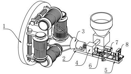
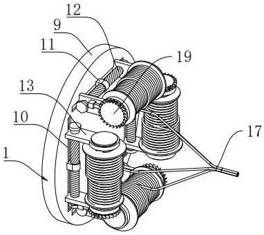
[0036] Such as figure 1 As shown, a kind of wire and cable insulation layer production extrusion molding processing equipment, including a pay-off assembly 1, the right side of the pay-off assembly 1 is provided with a mounting base plate 2, and the left side of the top of the mounting base plate 2 is fixedly installed with a straightening assembly 3, The right side of the top of the installation base plate 2 is provided with injection molding equipment 4, the...


PUM


Abstract

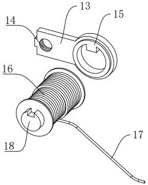
The invention relates to the technical field of cable insulation layers, and particularly discloses wire and cable insulation layer manufacturing extrusion forming processing equipment which comprises a pay-off assembly, a mounting bottom plate is arranged on the right side of the pay-off assembly, a straightening assembly is fixedly mounted on the left side of the top of the mounting bottom plate, and injection molding equipment is arranged on the right side of the top of the mounting bottom plate. A current collecting box is arranged on the right side of the mounting bottom plate, a pre-cooling assembly is arranged on the left side of the top of the current collecting box, a water cooling assembly is arranged on the right side of the pre-cooling assembly, and the mounting function of a winding roller can be completed by rotating a first threaded rod forwards and backwards, so that the winding roller is more convenient to disassemble; the battery cells can pull the winding roller to rotate, then the spline base is driven to rotate synchronously, the automatic paying-off function is achieved, the multiple sets of battery cells are guided into the straightening assembly, the multiple sets of battery cells are extruded to be tightly attached together, the bundling function of the battery cells is achieved, and it is guaranteed that the multiple sets of battery cells are tightly attached before injection molding.

Description

technical field [0001] The invention relates to the technical field of cable insulation layers, in particular to extrusion molding processing equipment for making wire and cable insulation layers. Background technique [0002] In order to prevent accidents such as short circuit and electric leakage during the use of the cable, it is necessary to evenly wrap a layer of non-conductive material on the periphery of the battery core. This layer of non-conductive material is usually called an insulating layer, and the insulating layer is usually formed by extrusion. Coated on the outside of the wire and cable. [0003] The existing cable insulation layer extrusion molding equipment has the following problems: 1. Before the existing cable insulation layer extrusion molding equipment is extruded, for soft wire and cable products, it is necessary to bundle the electric cores and then perform extrusion molding , The existing cell harness equipment has a poor alignment effect on the c...

Claims


Application Information

Patent Timeline
Patent Type & Authority Applications(China)
IPC IPC(8): B29C48/05B29C48/154B29C48/885B29C37/00H01B13/14H01B13/24
Inventor 王怀亮
Owner 徐州丰和新能源科技有限公司
Learn More