
Film coating equipment for photovoltaic solar module production and working method thereof

A photovoltaic solar energy and component technology, applied in photovoltaic power generation, electrical components, semiconductor devices, etc., can solve the problems of reducing the coating effect, low safety, low coating efficiency, etc., to improve the degree of automation, stable left and right movement, The effect of improving lamination efficiency

Active Publication Date: 2022-04-12
ANHUI GUOCHENG PHOTOELECTRIC TECH CO LTD
View PDF10 Cites 4 Cited by
  • Summary
  • Abstract
  • Description
  • Claims
  • Application Information

AI Technical Summary

Problems solved by technology

[0004]However, there are great defects in the use of the existing lamination equipment. The existing lamination equipment cannot be automated and streamlined for lamination operations. Manual operation is required in the filming process, which increases the labor burden of manpower and is prone to personal injury. The safety is not high. At the same time, it cannot be streamlined. The flexibility of the laminating equipment is not high during use, the feeding is not stable enough, and there is no stable support during the laminating process. At the same time, the position of the photovoltaic panel is not limited, and the alignment of the laminating film is easy to be inaccurate. The existing laminating equipment is easy to Bubbles appear, which reduces the effect of film covering. At the same time, no cushioning components are used in the film covering process, and the film is easy to break during film covering, which reduces the reliability of use.

Method used


Image

  • Film coating equipment for photovoltaic solar module production and working method thereof
  • Film coating equipment for photovoltaic solar module production and working method thereof
  • Film coating equipment for photovoltaic solar module production and working method thereof

Examples


Embodiment Construction

[0036] In order to make the technical means, creative features, goals and effects achieved by the present invention easy to understand, the present invention will be further described below in conjunction with specific embodiments.

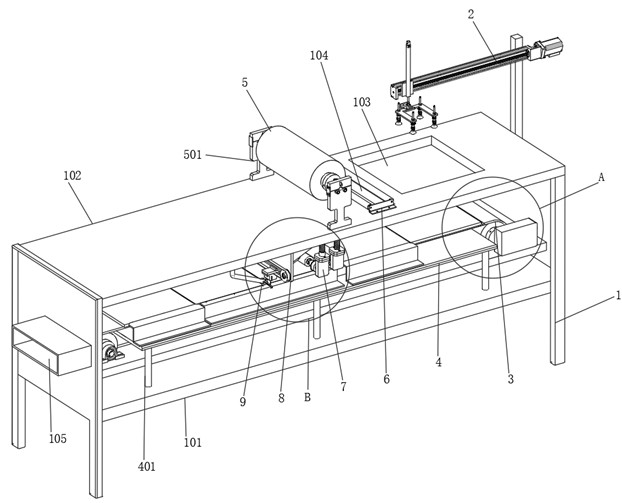
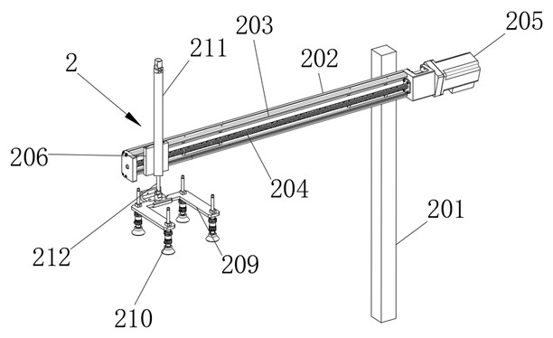
[0037] Such as Figure 1-Figure 10 As shown, a film covering equipment for photovoltaic solar module production according to the present invention includes a support frame 1, a feeding assembly 2, a conveying assembly 3, a film covering roller 5, a film covering assembly 7, a film cutting assembly 8 and a film pressing assembly Wheel 9, two support frames 1 are arranged in parallel, and the two support frames 1 are respectively horizontally welded with a support plate 101 and a top plate 102, and the top plate 102 is located on the top of the two support frames 1, and the top of the support plate 101 is equipped with a conveying assembly 3 , the bottom of the top plate 102 is located above the conveying assembly 3 and is respectively fixed with a ...


PUM


Abstract

The invention relates to the technical field of photovoltaic solar module film covering, in particular to film covering equipment for photovoltaic solar module production and a working method thereof.The film covering equipment comprises a supporting frame, a feeding assembly, a conveying assembly, a film covering roller, a film covering assembly, a film cutting assembly and a film pressing wheel; according to the film laminating equipment, the film laminating roller and the film laminating assembly are used for laminating in the conveying process, and the connected film is cut by the film cutting assembly, so that the film laminating equipment can be used for automatically laminating the photovoltaic solar panel in a streamlined manner, and all links of the film laminating equipment do not need to be manually operated by automatically laminating the film, so that the labor intensity of workers is reduced, and the production efficiency is improved. Compared with the prior art, labor is saved, meanwhile, the situation that personnel are hurt by the equipment or the photovoltaic solar panel in the manual operation process is avoided, and meanwhile, through film laminating streamline of the equipment, all links of film laminating of the equipment are matched more tightly, and the film laminating speed is higher.

Description

technical field [0001] The invention relates to the technical field of film covering of photovoltaic solar modules, in particular to a film covering equipment for producing photovoltaic solar modules and a working method thereof. Background technique [0002] Photovoltaic solar module is a power generation device that generates direct current when exposed to sunlight. It is composed of thin solid photovoltaic cells almost entirely made of semiconductor materials. During transportation, in order to avoid surface wear of photovoltaic solar modules, it is usually used The film coating equipment covers it, and the transparent plastic film is pasted on the surface of the photovoltaic solar module through the film coating equipment, which can protect and increase the gloss of the photovoltaic solar module, and avoid the wear and tear of the photovoltaic solar module during transportation and affect the power generation effect. [0003] The Chinese patent with the application numbe...

Claims


Application Information

Patent Timeline
Patent Type & Authority Applications(China)
IPC IPC(8): B29C63/02B29C63/00H01L31/048
CPCY02E10/50Y02P70/50
Inventor 杨瑞王茹兰飞陈芬王丽
Owner ANHUI GUOCHENG PHOTOELECTRIC TECH CO LTD
Learn More