
Suspension structure and vehicle

A suspension and link mechanism technology, applied in the field of vehicles, can solve the problems of reduced vibration isolation performance, inability to increase the diameter of the bushing, and increased stiffness, and achieve the effect of improving the vibration isolation performance

Pending Publication Date: 2022-04-12
ZHEJIANG GEELY HLDG GRP CO LTD +1
View PDF0 Cites 0 Cited by
  • Summary
  • Abstract
  • Description
  • Claims
  • Application Information

AI Technical Summary

Problems solved by technology

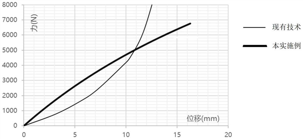
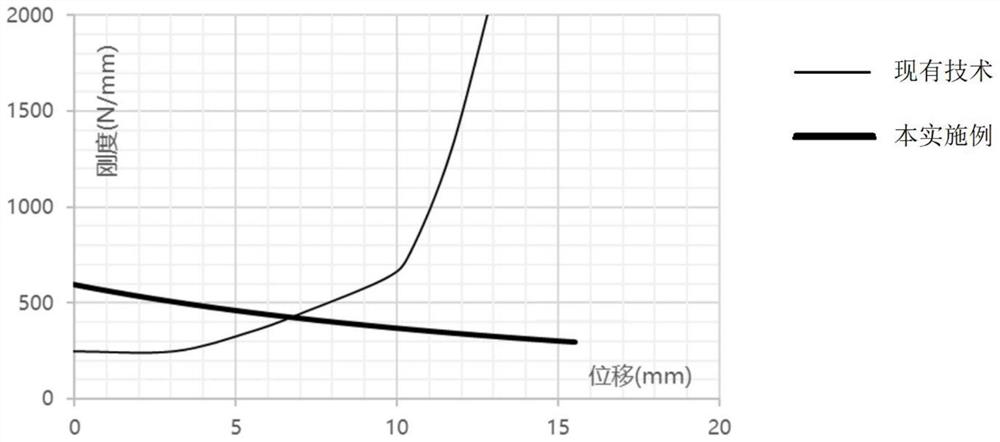
It can be seen from the structure that when the powertrain is turned over, the active end bracket drives the rubber main spring to collide with the passive side frame to limit the position, but at the same time the rubber main spring is squeezed, and the stiffness will increase rapidly, resulting in the vibration isolation performance of the suspension structure become worse
[0004] The inventor found that in the traditional design of the suspension structure, the vibration isolation performance of the bushing is improved by increasing the diameter of the bushing or changing the rubber shape of the limit block, and increasing the thickness of the rubber material. However, due to the limitation of the cabin space and cost reasons, it cannot Limited oversized bushing diameter
In addition, the output torque of current hybrid and electric vehicles is large, and the stiffness of the suspension increases significantly under the condition of large torque, resulting in a decrease in vibration isolation performance and affecting the level of vibration and noise in the vehicle

Method used


Image

  • Suspension structure and vehicle
  • Suspension structure and vehicle
  • Suspension structure and vehicle

Examples


Embodiment Construction

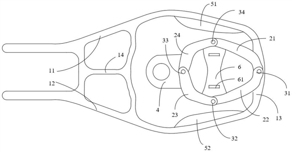
[0046] figure 1 is a schematic structural diagram of a suspension structure according to an embodiment of the present invention. The suspension structure may generally include an active end bracket, a passive end bracket 4, a double rocker mechanism and an elastic element. The active end bracket is connected to the passive end bracket 4 through a double rocker mechanism, and the active end bracket is connected to the powertrain. The end bracket 4 is fixed on the vehicle body or the sub-frame; the double rocker mechanism includes four connecting rods arranged in a diamond shape, and adjacent connecting rods are connected by hinges.

[0047] In this embodiment, the active end bracket includes a first bracket part 11, a second bracket part 12 and a third bracket part 13, wherein the third bracket part 13 is U-shaped, and the first bracket part 11 and the second bracket part 12 are respectively connected At both ends of the third support portion 13 , both the first support portio...


PUM


Abstract

The invention provides a suspension structure and a vehicle, and belongs to the field of vehicles, the suspension structure comprises a driving end support, a driven end support, a connecting rod mechanism and an elastic element, the driven end support is connected with the driving end support through the connecting rod mechanism, and at least one pair of hinge points with opposite movement directions of the connecting rod mechanism are connected through the elastic element; a limiting elastic unit is further arranged on the inner wall of the driving end support. The elastic force providing direction of the suspension structure can be changed, the rigidity of a suspension system can be smaller when the stress is larger, and the vibration isolation performance of the suspension system is improved under the working condition of large torque.

Description

technical field [0001] The invention relates to the field of vehicles, in particular to a suspension structure and a vehicle. Background technique [0002] The main function of the suspension system of the powertrain is to limit the displacement of the powertrain and avoid interference between the powertrain and other components. However, the suspension system, as the connection between the engine and the body, should have a good vibration isolation effect to reduce the excitation transmitted from the engine to the body. From the point of view of limitation, considering the limited space structure, the target expectation is that the hardness of the suspension system is as large as possible, and the total displacement of the engine is as small as possible; from the perspective of vibration isolation, the goal is to make the suspension system as flexible as possible and as rigid as possible Small. [0003] The inventor found that the current suspension structure is composed ...

Claims


Application Information

Patent Timeline
IPC IPC(8): B60K5/12
Inventor 赵珂谢凯石代云毛杰柏福明徐旭超
Owner ZHEJIANG GEELY HLDG GRP CO LTD
Learn More