Parking apron mechanical laying system and method
A laying method and apron technology, applied in the directions of roads, road repair, roads, etc., can solve the problems of long laying and retracting time and high work intensity, and achieve the effect of low laying work intensity, long work time and fast speed.
- Summary
- Abstract
- Description
- Claims
- Application Information
AI Technical Summary
Problems solved by technology
Method used
Image

Examples
Embodiment 1
[0028] This embodiment provides a mechanized laying system for an apron. With this system, an apron suitable for a helicopter with a take-off and landing weight of 13 tons can be quickly laid on sandy beaches, muddy areas, snowy areas and other areas with low load capacity; the laying operation is less intensive and faster.
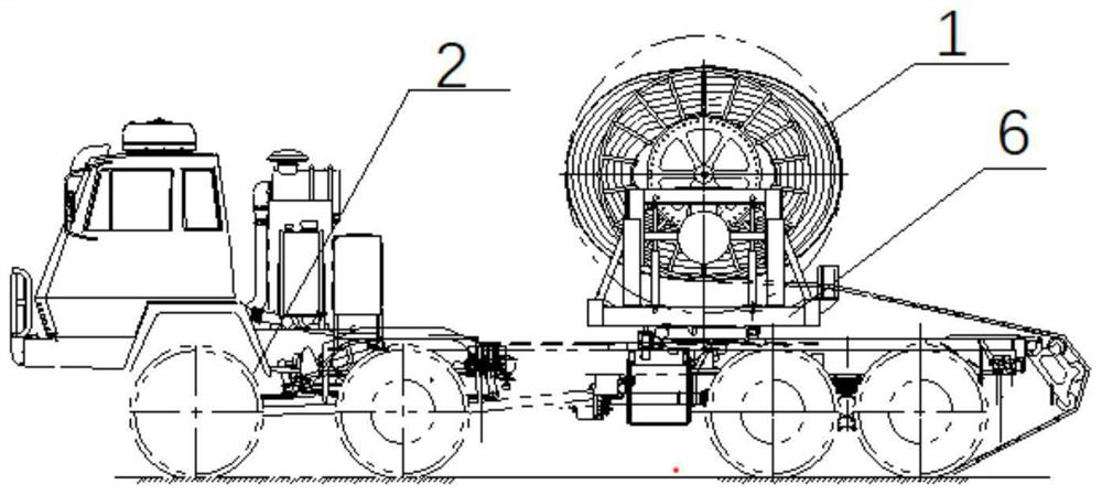
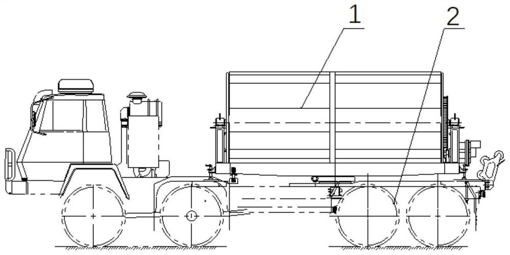
[0029] Such as figure 1 and figure 2 As shown, the laying system includes: a plurality of apron unit boards 1, a laying vehicle 2, a laying withdrawal device 6 and connecting pieces.
[0030] In order to realize the mechanized laying of the apron, the apron is designed in a modular manner, that is, the apron unit board 1 is designed, and the apron is formed by splicing a plurality of apron unit boards 1 longitudinally and laterally.
[0031] The paving vehicle 2 is provided with a paving and withdrawing device 6, and a plurality of apron unit panels 1 are longitudinally connected and then rolled up on the reel of the paving and withdrawing device 6; the...
Embodiment 2
[0037] The method of using the above-mentioned apron mechanized laying system to carry out the mechanized laying of the apron is as follows:
[0038] First, a plurality of apron unit panels 1 are longitudinally connected and rolled up on the reel of the laying and withdrawing device; then the laying vehicle 2 is driven to the set position;
[0039] Then according to the length of the apron to be laid, the apron unit plate 1 of the corresponding number is released by controlling the laying and withdrawing device (the length required to be laid should be an integer multiple of the length of a single apron unit plate 1); The length should be N times the length of a single apron unit plate 1, then release N pieces of apron unit plate 1 each time;
[0040] Disconnect the longitudinal connection between the Nth apron unit board 1 and the N+1 apron unit board 1; then drive the laying vehicle 2 and move the distance of one apron unit board 1 laterally; then control the paving and with...
Embodiment 3
[0044] On the basis of above-mentioned embodiment 1 or embodiment 2, further:
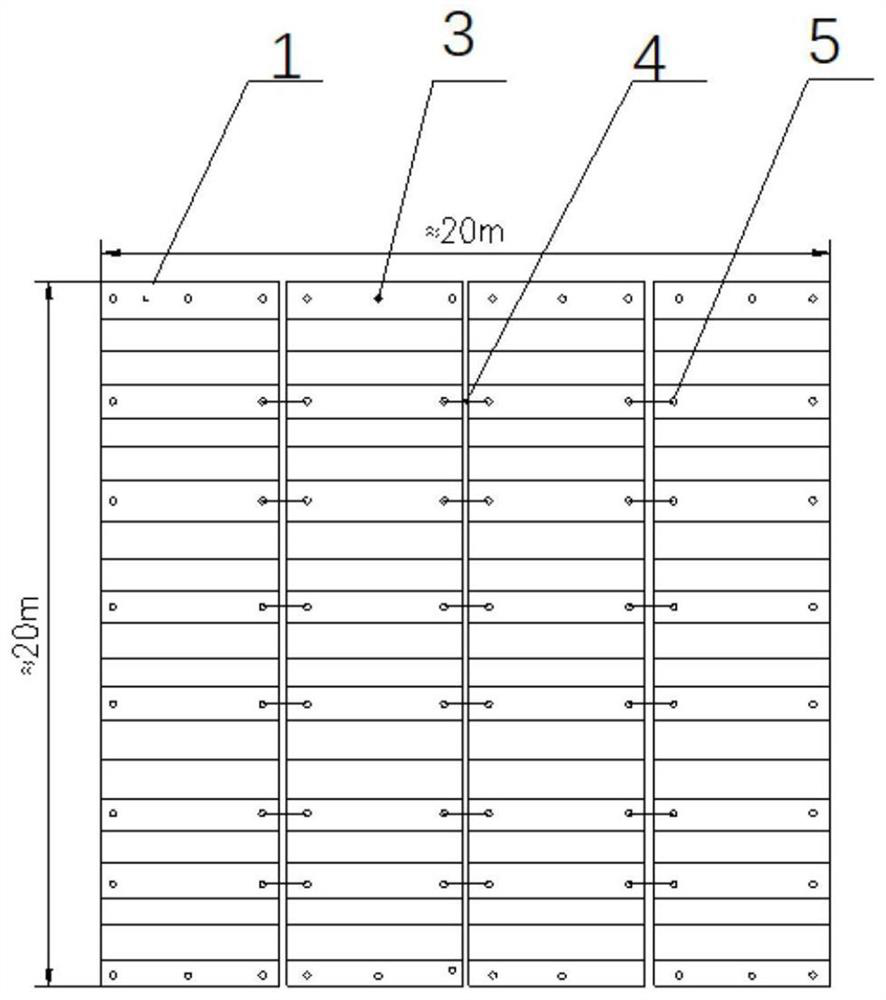
[0045] In order to facilitate the disconnection between the last apron unit board 1 of each row and the first apron unit board 1 of the next row during laying (disconnecting the C-D joint, the operation is more complicated); when the apron to be laid is known in advance Under the premise of length, if it is known that the length of the apron to be laid is N times the length of a single apron unit plate 1, then the N apron unit plates 1 are grouped, and two adjacent apron units are in each group The plates 1 are still connected longitudinally by C-D joints, between the two apron unit plates 1 between each group (that is, between the last apron unit plate 1 of the previous group and the first apron unit plate 1 of the next group ) are connected by a vertical connector 7 that is convenient to disassemble. The two ends of the longitudinal connector 7 are connecting clips in the shape of a butt joint, ...
PUM
 Abstract
Description
Claims
Application Information
 - R&D Engineer
- R&D Manager
- IP Professional
- Industry Leading Data Capabilities
- Powerful AI technology
- Patent DNA Extraction
Browse by: Latest US Patents, China's latest patents, Technical Efficacy Thesaurus, Application Domain, Technology Topic.
© 2024 PatSnap. All rights reserved.Legal|Privacy policy|Modern Slavery Act Transparency Statement|Sitemap