
Axial fixing structure of static pressure main shaft

An axially fixed, hydrostatic spindle technology, applied to shafts and bearings, bearing components, bearing cooling, etc., can solve the problems of easy loss of accuracy, high processing difficulty, spindle lock, etc., to reduce processing difficulty and improve processing efficiency. , Improve the effect of fever and lock-up

Pending Publication Date: 2022-04-12
湖南高创海捷工程技术有限公司
View PDF0 Cites 0 Cited by
  • Summary
  • Abstract
  • Description
  • Claims
  • Application Information

AI Technical Summary

Problems solved by technology

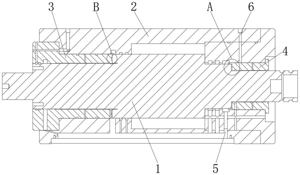
[0003] Hydrostatic bearings commonly used in machine tools, the front and rear bearings are fixed on the box body, the oil inlet holes set on the box body are connected to the ring grooves on the outer circles of the front and rear bearings, and the pressure oil enters the bearings through the small holes opened on the ring grooves In the inner cavity, an oil film is formed to cover the rotation of the main shaft, and the positioning between the main shaft and the bearing in the prior art is realized in this way: the end cover of the main shaft shoulder and the front bearing are positioned, and the end face of the end cover and the front bearing and the shaft shoulder fit There is an end face static pressure oil chamber, which is filled with pressure oil to form an oil film during operation, which plays the role of axial positioning of the end face bearing. Adjusting pads are used to adjust the width of the main shaft shoulder, the end cover and the end face static pressure oil chamber on the front bearing. The gap between them enables them to achieve the ideal design value when they cooperate. The shaft is a high-speed rotating part with high precision. In order to achieve normal work according to the design requirements, it is necessary to strictly control the precision of the matching parts. It is necessary to match the grinding pad during processing. The precision is usually Measured at 0.01mm and below, the processing is very difficult and the efficiency is low. Not only that, because the radial static pressure oil chamber and the end face static pressure oil chamber are concentrated, when the spindle rotates at high speed, the heat is concentrated, and the accuracy of the material is easy to lose after thermal expansion. , causing the spindle to lock

Method used


Image

  • Axial fixing structure of static pressure main shaft
  • Axial fixing structure of static pressure main shaft
  • Axial fixing structure of static pressure main shaft

Examples


Embodiment Construction

[0031] The following will clearly and completely describe the technical solutions in the embodiments of the present invention with reference to the accompanying drawings in the embodiments of the present invention. Obviously, the described embodiments are only some, not all, embodiments of the present invention. Based on the embodiments of the present invention, all other embodiments obtained by persons of ordinary skill in the art without making creative efforts belong to the protection scope of the present invention.

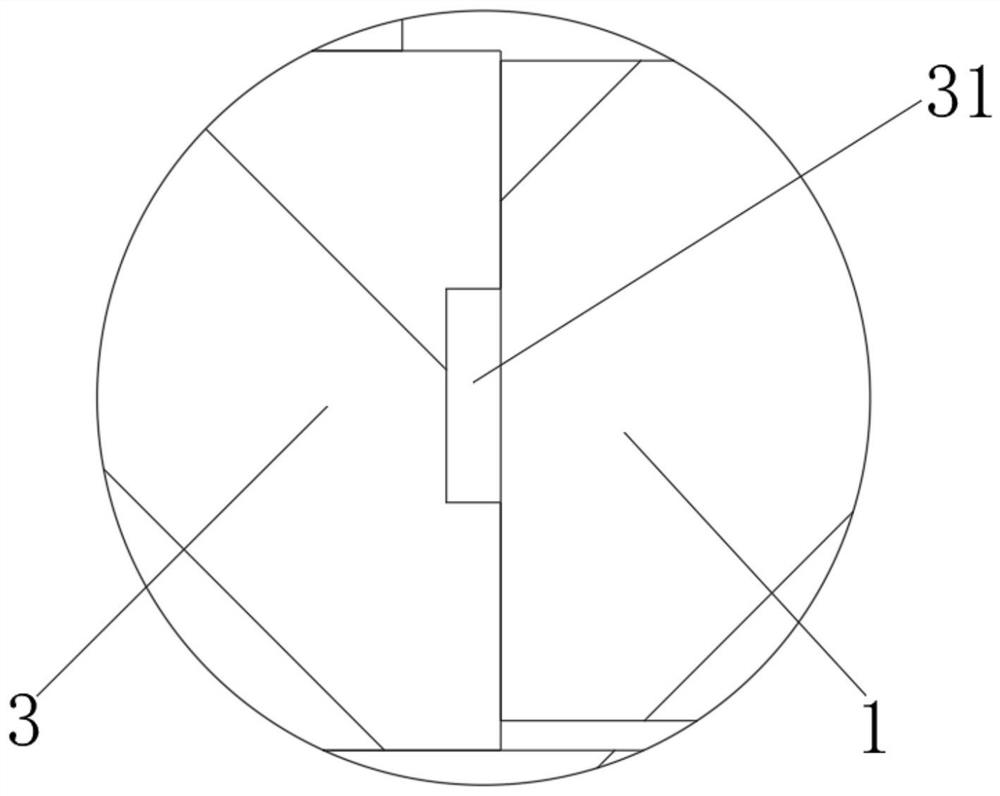
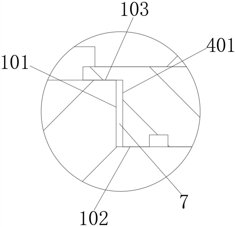
[0032] Such as Figure 1 to Figure 7As shown, in the embodiment of the present invention, a hydrostatic spindle axially fixed structure includes a spindle 1, a pressure pump 11, a casing 2 fixedly installed outside the spindle 1 and an oil inlet hole 5 opened on the casing 2, The front and rear bearings 3 and 4 are fixedly installed at both ends of the box body 2, respectively. The front bearing 3 is provided with a static pressure oil chamber 31 on the opposi...


PUM


Abstract

The invention belongs to the technical field of hydrostatic bearings, and discloses a hydrostatic spindle axial fixing structure which comprises a spindle, a pressure pump, a box fixedly mounted outside the spindle and an oil inlet formed in the box, and a front bearing and a rear bearing are fixedly mounted at the front end and the rear end of the box respectively. The first step end face, the first throttling edge and the second throttling edge at the rear end of the main shaft and the second step end face of the rear bearing jointly define the end face gap, and pressure oil is forcibly pumped into the end face gap, so that two original end face throttling cavities are concentrated to one position, an end face throttling cavity and double radial throttling edges are formed, and the pressure oil is forcibly pumped into the end face gap. The step end face of the bearing and the step end face of the main shaft are arranged in a staggered mode, the positions are scattered in front and back, the situation that the main shaft is locked due to heating can be greatly improved, the gap width between the step end face of the bearing and the step end face of the main shaft is 0.5-1 mm, machining is easy, machining difficulty is greatly reduced, and machining efficiency is improved.

Description

technical field [0001] The invention belongs to the technical field of static pressure bearings, in particular to an axial fixing structure of a static pressure main shaft. Background technique [0002] Hydrostatic bearing is a kind of sliding bearing, which uses pressure to forcibly pump pressure oil into the gap between the bearing and the shaft. [0003] Hydrostatic bearings commonly used in machine tools, the front and rear bearings are fixed on the box body, the oil inlet holes set on the box body are connected to the ring grooves on the outer circles of the front and rear bearings, and the pressure oil enters the bearings through the small holes opened on the ring grooves In the inner cavity, an oil film is formed to cover the rotation of the main shaft, and the positioning between the main shaft and the bearing in the prior art is realized in this way: the end cover of the main shaft shoulder and the front bearing are positioned, and the end face of the end cover and ...

Claims


Application Information

Patent Timeline
Patent Type & Authority Applications(China)
IPC IPC(8): F16C35/10F16C37/00
Inventor 彭克立谢萍吕国庆刘萍施毅
Owner 湖南高创海捷工程技术有限公司
Learn More