Double-layer built-in reinforced HDPE winding pipe

A winding pipe and double-layer technology, which is applied in the direction of pipes, rigid pipes, pipes/pipe joints/pipe fittings, etc., can solve the problems of insufficient strength of HDPE winding pipes, insufficient firmness of welding joints, and long connection seams of winding pipes, etc., to achieve improvement The effect of connection firmness, improved anti-deformation ability, and reasonable structure setting

Pending Publication Date: 2022-04-12
金玉玲
View PDF0 Cites 0 Cited by
  • Summary
  • Abstract
  • Description
  • Claims
  • Application Information

AI Technical Summary

Problems solved by technology

[0008] The purpose of the present invention is to provide a double-layer built-in reinforced HDPE winding pipe to solve the insufficient strength of the HDPE winding pipe proposed in the above background technology. When performing landfill installation, the pipe is easily deformed by external forces such as soil, resulting in The place of use is limited; the connection seam of the winding pipe itself is very long, and the firmness of the weld is not enough, and it is easy to break under the action of external force.

Method used


Image

  • Double-layer built-in reinforced HDPE winding pipe
  • Double-layer built-in reinforced HDPE winding pipe
  • Double-layer built-in reinforced HDPE winding pipe

Examples


specific Embodiment approach 1

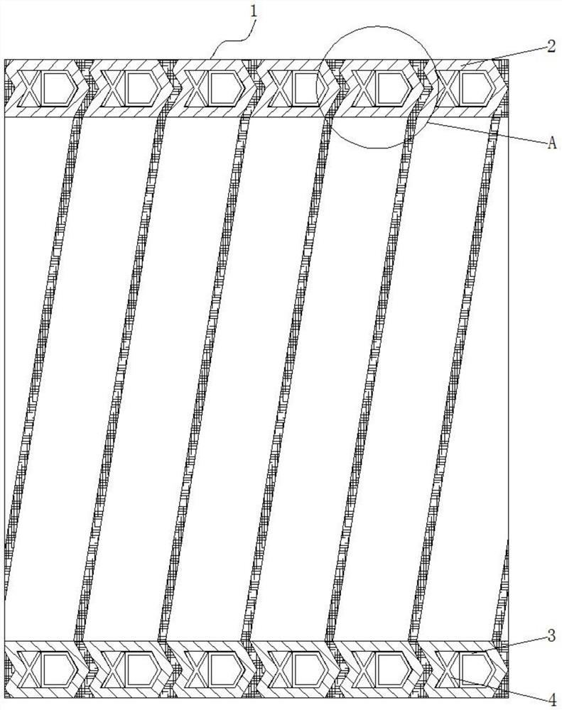
[0033] Specific implementation mode one: please refer to Figure 1-4 , the present invention provides a technical solution: a double-layer built-in reinforced HDPE winding pipe, including:

[0034] The winding pipe body 1, the winding pipe body 1 includes a helically wound hollow pipe 2 and a first reinforcement 3, the inner wall of the winding pipe body 1 is the bottom surface of the hollow pipe 2, and the outer surface of the winding pipe body 1 is the top surface of the hollow pipe 2 ;

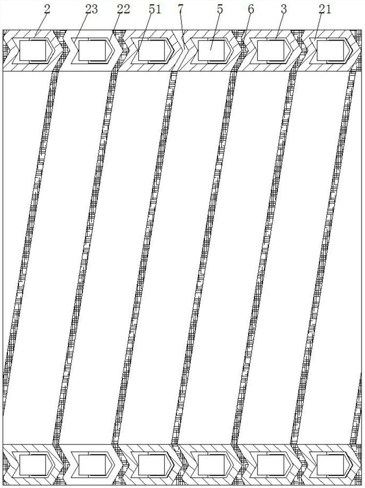
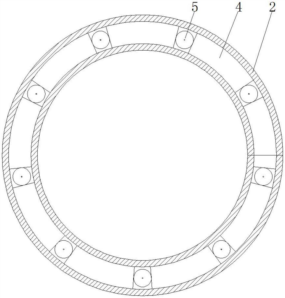
[0035] Hollow tube 2, a lumen 21 is formed inside the hollow tube 2, a first reinforcing member 3, a second reinforcing member 4 and a partition tube 5 are arranged in the lumen 21, and a cut surface 26 is arranged at the upper left corner of the hollow tube 2;

[0036] The first reinforcement 3 is embedded in the lumen 21, and the right side of the first reinforcement 3 is attached to the inner concave surface 22;

[0037] The second reinforcement 4, the right end of the second reinforce...

specific Embodiment approach 2

[0041] Specific embodiment two: this embodiment is a further limitation of specific embodiment one, such as figure 1 , figure 2 and Figure 4 As shown, the cross section of the hollow tube 2 is a dovetail-like structure, the hollow tube 2 is made of HDPE material, the upper and lower sides of the hollow tube 2 are horizontal planes, the left and right sides of the hollow tube 2 are V-shaped surfaces, and the tip of the V-shaped surface They are all set to the right, the left V-shaped surface is the outer concave surface 25, the right V-shaped surface is the outer convex surface 24, the outer convex surface 24 and the outer concave surface 25 correspond to the inner concave surface 22 and the inner convex surface 23 in the lumen 21 respectively, and the V-shaped surface is set. Two adjacent turns of the hollow tube 2 form an overlapping structure. When a certain turn of the hollow tube 2 is under pressure, the adjacent turn of the hollow tube 2 can provide a supporting force ...

specific Embodiment approach 3

[0042] Specific implementation mode three: this implementation mode is a further limitation of specific implementation mode two, such as Figure 4 As shown, the outer concave surface 25 is connected to the cut surface 26, the outer concave surface 25 and the outer convex surface 24 on two adjacent hollow tubes 2 are facing each other, and the distance between the outer convex surface 24 and the cut surface 26 is greater than that between the outer convex surface 24 and the outer concave surface 25. The cutting surface 26 increases the tortuosity of the outer convex surface 24, and the gap 7 at the cutting surface 26 is larger in size, which is convenient for injecting the adhesive material 6 into the gap 7 from the outside to the inside, increasing the bonding area and improving the hollow tube 2. connection firmness.


PUM


Abstract

The invention discloses a double-layer built-in reinforced HDPE (high-density polyethylene) winding pipe which comprises a winding pipe body, and the winding pipe body comprises a spirally-wound hollow pipe and a first reinforcing part; a pipe cavity is formed in the hollow pipe; the first reinforcing piece is embedded in the pipe cavity, and the right side face of the first reinforcing piece is attached to the inner concave face; the right end of the second reinforcing part is close to the first reinforcing part; the separating cylinder is inserted into the left side surface of the first reinforcing piece; and the gap is filled with the bonding material, and the bonding material is used for connecting the outer convex surface and the outer concave surface. According to the double-layer built-in reinforced HDPE winding pipe, the inner wall of the hollow pipe is supported through the first reinforcing piece and the second reinforcing piece, the pipe wall strength of the winding pipe is effectively improved, and when the winding pipe is subjected to the acting force perpendicular to the pipe wall, the reinforcing pieces change the transmission direction of part of the acting force through the inclined faces, so that the acting force is transmitted in the direction of the winding pipe; the effect of dispersing the acting force is achieved.

Description

technical field [0001] The invention relates to the related technical field of winding pipes, in particular to a double-layered HDPE winding pipe with built-in reinforcement. Background technique [0002] The HDPE winding pipe uses high-density polyethylene resin (HDPE) as the raw material, and the tape made of HDPE is wound on the winding pipe forming machine, and at the same time, the molten adhesive is filled in the spiral gap of the tape by the extruder. Bonding to form HDPE winding pipe. [0003] In recent years, HDPE winding pipes have developed very rapidly. Compared with traditional concrete and metal pipes, HDPE winding pipes have many advantages and become the drainage pipes that are vigorously promoted in my country. Its wide application is conducive to saving energy, reducing pollution and protecting the environment. . [0004] However, the HDPE winding pipes of the prior art mainly have the following disadvantages: [0005] 1. The strength of HDPE winding pipe...

Claims


Application Information

Patent Timeline
Patent Type & Authority Applications(China)
IPC IPC(8): F16L9/16
Inventor 金玉玲
Owner 金玉玲
Why Eureka
Try Eureka