Supercharge Your Innovation With Domain-Expert AI Agents!

High-reliability module system

A reliability and module technology, applied in the loss prevention measures of lighting devices, lighting and heating equipment, light sources, etc., can solve the problems of reduced reliability of LED modules, failure of LED modules, dark crack safety distance, etc. Achieve the effect of avoiding poor assembly and optical anomalies, avoiding hidden anomalies, and realizing labor costs

Pending Publication Date: 2022-04-12
联晶智能电子有限公司
View PDF0 Cites 0 Cited by
  • Summary
  • Abstract
  • Description
  • Claims
  • Application Information

AI Technical Summary

Problems solved by technology

[0002] As we all know, in order to further reduce the labor cost of assembly and manufacturing and raw material cost, most lighting assembly factories simplify the process technology and raw material performance of the indispensable materials of LED modules. Therefore, while considering the cost factor, Neglecting the most important quality issues such as product reliability, resulting in a large number of product failures during the use of end users, resulting in very large economic losses
[0003] During the assembly and manufacturing process of such products, the LED-integrated light-emitting module or COB light source is generally directly fixed on the radiator with screws. Due to the large tolerance of the flatness of the radiator surface, effective coaxiality positioning cannot be performed. Very large internal stress, such as shear stress in the normal direction of the axis, leads to dark cracks in the LED integrated light-emitting module or the PCB of the COB light source, or the safety distance becomes smaller, resulting in leakage, or due to excessive coaxiality tolerance , resulting in the optical effect failing to meet the performance requirements, etc., which greatly reduces the reliability of the LED module, and eventually leads to the failure of the LED module

Method used


Image

  • High-reliability module system
  • High-reliability module system
  • High-reliability module system

Examples


Embodiment Construction

[0032] The preferred embodiments of the present invention will be described below in conjunction with the accompanying drawings. It should be understood that the preferred embodiments described here are only used to illustrate and explain the present invention, and are not intended to limit the present invention.

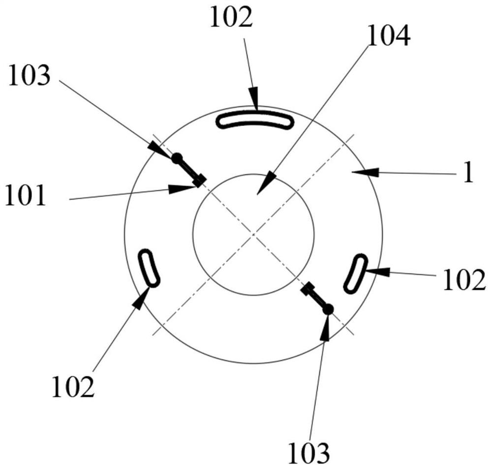
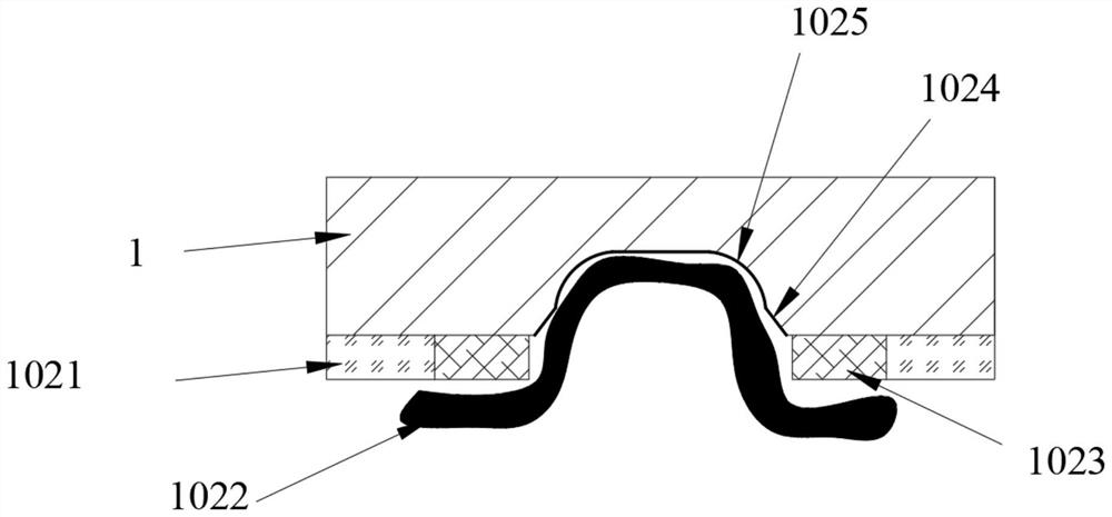
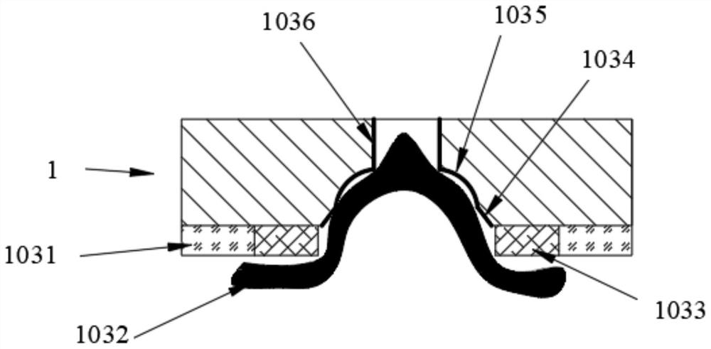
[0033] A system and its implementation method that can improve the reliability of LED modules described in the present invention can realize the separation of the LED integrated light-emitting module or COB light source from the base, and avoid the coaxiality tolerance between the components. The failure caused by too large can effectively control the coaxiality accuracy between the base and the gland, as well as the LED-integrated light-emitting module or COB light source, avoid poor assembly and optical abnormalities caused by misalignment, and improve the reliability of the LED module;

[0034] It can reduce the labor cost of the assembly and manufacturing factory...


PUM


Abstract

The invention provides a high-reliability module system. The high-reliability module system comprises at least one gland, at least one base, an LED light-emitting module and a COB light source. A plurality of first vector bonding pads are arranged in the gland; a solder paste layer is arranged on the first vector bonding pad in a covering manner, and the first vector bonding pad is electrically connected and fixed with the base through reflow soldering; the base is provided with a connecting device which is electrically connected with an external driving device; the base is provided with a plurality of second vector bonding pads; a solder paste layer is arranged on the second vector bonding pad in a covering manner, and the second vector bonding pad is electrically connected and fixed with the gland through reflow soldering; the coaxiality precision between the base and the gland and between the LED integrated light-emitting module or the COB light source can be effectively controlled, poor assembly and optical abnormity caused by dislocation are avoided, and the reliability of the LED module is improved.

Description

technical field [0001] The invention relates to the field of LED lighting modules, in particular to a high-reliability module system. Background technique [0002] As we all know, in order to further reduce the labor cost of assembly and manufacturing and raw material cost, most lighting assembly factories simplify the process technology and raw material performance of the indispensable materials of LED modules. Therefore, while considering the cost factor, The most important quality issues such as product reliability are ignored, resulting in a large number of product failures during the use of end users, resulting in very large economic losses. [0003] During the assembly and manufacturing process of such products, the LED-integrated light-emitting module or COB light source is generally directly fixed on the radiator with screws. Due to the large tolerance of the flatness of the radiator surface, effective coaxiality positioning cannot be performed. Very large internal ...

Claims


Application Information

Patent Timeline
Patent Type & Authority Applications(China)
IPC IPC(8): F21K9/20F21V19/00F21V15/01F21V17/10F21V23/06F21Y115/10
Inventor 刘贤金郑永生侯宇曾照明肖国伟
Owner 联晶智能电子有限公司
Features
  • R&D
  • Intellectual Property
  • Life Sciences
  • Materials
  • Tech Scout
  • Unparalleled Data Quality
  • Higher Quality Content
  • 60% Fewer Hallucinations
Learn More