Micro leakage flow automatic detection device and detection method thereof

A technology of automatic detection and metering device, which is applied in the direction of measuring the acceleration and deceleration rate of fluid and using liquid/vacuum degree for liquid tightness measurement, etc., can solve the problems of inconvenient leakage detection, poor detection accuracy and low efficiency, etc. Achieve a wide range of objects and working conditions, improve efficiency and accuracy

Pending Publication Date: 2022-04-12
GUANGDONG NACRE HYDRAULIC CO LTD
View PDF0 Cites 0 Cited by
  • Summary
  • Abstract
  • Description
  • Claims
  • Application Information

AI Technical Summary

Problems solved by technology

[0002] In the fluid field, there are many fluid power components, executive components, and fluid pressure, flow, and direction control components, all of which have problems of external leakage and internal leakage; especially internal leakage, due to the amount of leakage Small size, inconvenient leakage detection, no corresponding flow measurement device, often can only use measuring cups and other measuring containers; not only poor detection accuracy, low efficiency, but also labor-intensive; therefore, how to efficiently detect internal leakage has always been a problem Important directions for continued research in this field
[0003] Among the detection methods in the prior art, a real-time monitoring device and method for the leakage of a hydraulic cylinder is announced. A cumulative high-pressure flowmeter is installed in the oil path from the reversing valve to the rodless chamber of the hydraulic cylinder; The linear displacement sensor used to detect the displacement of the piston rod of the hydraulic cylinder; the linear displacement sensor and the cumulative high-pressure flowmeter transmit signals to the PLC controller; the actual displacement value is compared with the theoretical displacement value through the PLC controller, and the difference is converted into internal leakage In this way, the leakage in the hydraulic cylinder is monitored in real time; on the one hand, there are multiple errors such as the error of the theoretical displacement value itself, the error of the actual displacement value itself, and the error accumulated during the use of the cylinder in the process of wear and tear on the measurement accuracy of the internal leakage. On the other hand, this method needs to be carried out under the condition that the piston rod of the hydraulic cylinder is fully extended by the fluid, which is only suitable for the monitoring of a very small number of components such as hydraulic cylinders, and cannot meet the needs of universality, and the value of promotion and application is low

Method used


Image

  • Micro leakage flow automatic detection device and detection method thereof
  • Micro leakage flow automatic detection device and detection method thereof
  • Micro leakage flow automatic detection device and detection method thereof

Examples


Embodiment 1

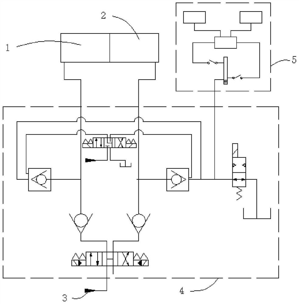
[0039] Such as figure 1 As shown, an automatic detection device for small leakage flow is used to detect the leakage rate between the first cavity 1 and the second cavity 2, including a liquid source 3, a fluid pipeline control device 4 and a metering device 5; The output end of the liquid source 3 is connected to the first cavity 1 and the second cavity 2 through a fluid pipeline;

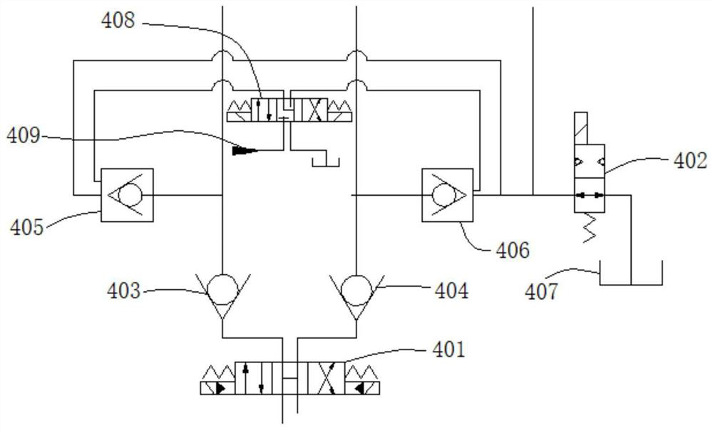
[0040] Such as figure 2 As shown, the fluid pipeline control device includes a first reversing valve 401, a solenoid valve 402, a first one-way valve 403, a second one-way valve 404, a first controllable one-way valve 405, a second controllable one-way valve 406;

[0041] The output end of the liquid source 3 is connected to the input end of the first reversing valve 401, the first outlet of the output end of the first reversing valve 401 is connected to the liquid inlet of the first one-way valve 403, and the liquid outlets of the first one-way valve 403 are respectively Access to the first c...

Embodiment 2

[0058] Such as Figure 4 As shown, this embodiment provides a detection method for an automatic detection device for micro-leakage flow, including the following steps:

[0059] S1: The liquid source 3 is started, and the power fluid is output to the first chamber 1 or the second chamber 2;

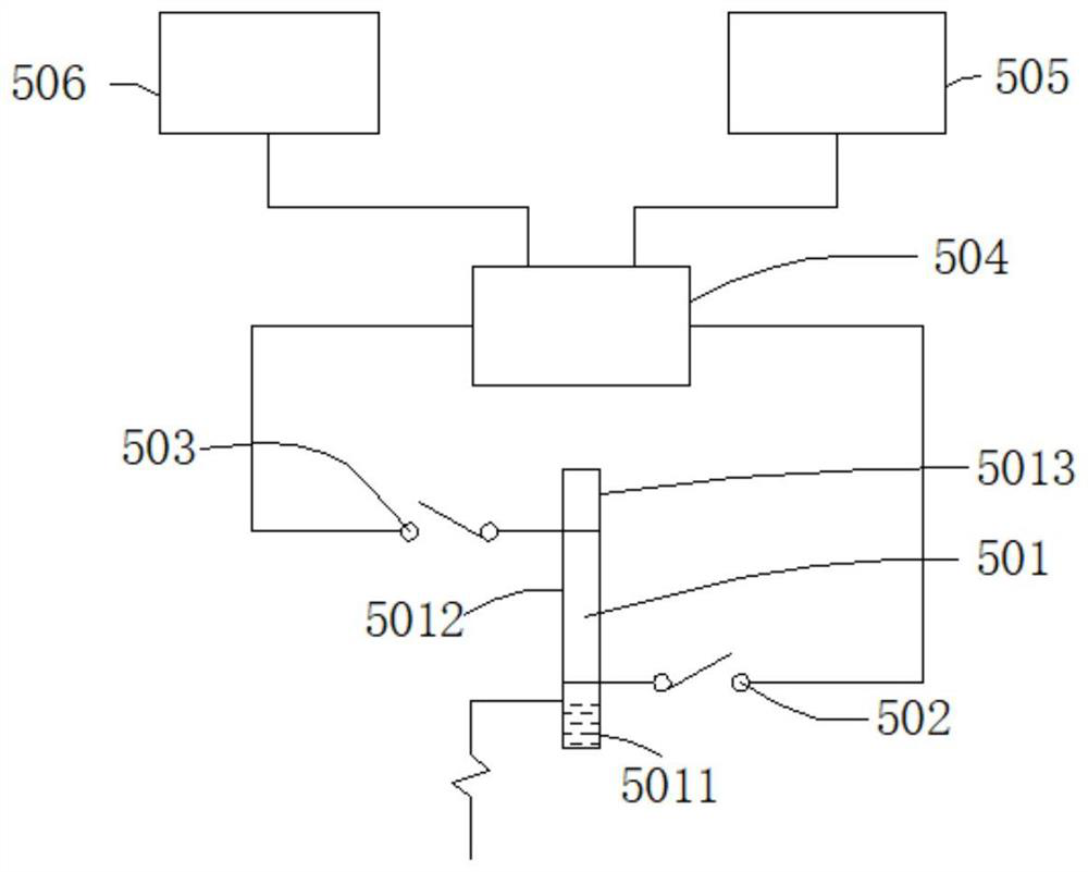
[0060] S2: The leakage fluid from the first cavity 1 or the second cavity 2 enters the metering device 5 through the fluid pipeline control device;

[0061] S3: The metering device 5 completes the metering, feeds back the metering result, and controls the solenoid valve 402 to open at the same time, and the leakage fluid is discharged to the liquid collection container 407 through the solenoid valve 402, and the detection is completed.

[0062] Step S2 includes the following two testing schemes:

[0063] When testing the leakage of the first cavity 1, the first outlet of the output end of the first reversing valve 401 is connected, and the power fluid enters the first cavity 1 through th...

Embodiment 3

[0077] The detection device and detection method of the present invention are suitable for internal leakage testing of oil cylinders, valves, motors, and pumps. This embodiment provides the application and implementation of leakage detection in hydraulic cylinders;

[0078] An automatic detection device for tiny leakage flow, used to detect the leakage rate between the first cavity 1 and the second cavity 2, including a liquid source 3, a fluid pipeline control device 4 and a metering device 5; the liquid source 3 The output end is connected with the first cavity 1 and the second cavity 2 through a fluid pipeline;

[0079] The fluid pipeline control device 4 includes a first reversing valve 401, a solenoid valve 402, a first one-way valve 403, a second one-way valve 404, a first controllable one-way valve 405, a second controllable one-way valve 406, Liquid collection container 407, second reversing valve 408 and control oil source 409;

[0080] The output end of the liquid s...


PUM


Abstract

The invention provides a micro leakage flow automatic detection device which is used for detecting the leakage rate between a first cavity and a second cavity and comprises a liquid source, a fluid pipeline control device and a metering device. The output end of the liquid source is communicated with any one of the first cavity and the second cavity through a fluid pipeline, the other cavity is a testing cavity, the liquid source injects fluid into the cavity connected with the liquid source, the fluid leaks into the testing cavity from the inside, and during testing, the electromagnetic valve is closed so that the internal leakage fluid can only flow into the metering device. After the test is finished, the electromagnetic valve is opened to discharge the leakage fluid, and the metering device is emptied to facilitate the next detection; according to the invention, the automatic detection of the micro leakage flow can be realized without manual intervention, the detection efficiency and precision are greatly improved, and the testable object and working condition range is wider.

Description

technical field [0001] The invention relates to the field of fluid technology, and more specifically, to an automatic detection device and a detection method for micro-leakage flow. Background technique [0002] In the fluid field, there are many fluid power components, executive components, and fluid pressure, flow, and direction control components, all of which have problems of external leakage and internal leakage; especially internal leakage, due to the amount of leakage Small size, inconvenient leakage detection, no corresponding flow measurement device, often can only use measuring cups and other measuring containers; not only poor detection accuracy, low efficiency, but also labor-intensive; therefore, how to efficiently detect internal leakage has always been a problem An important direction for continuing research in this field. [0003] Among the detection methods in the prior art, a real-time monitoring device and method for the leakage of a hydraulic cylinder is...

Claims


Application Information

Patent Timeline
Patent Type & Authority Applications(China)
IPC IPC(8): G01M3/26
Inventor 付巍黄力
Owner GUANGDONG NACRE HYDRAULIC CO LTD
Why Eureka
Try Eureka