
Photoelectric detector testing device and testing method

A technology of photodetectors and testing devices, which is applied in the field of sensors and can solve the problems of high cost of linearity evaluation of photodetectors

Pending Publication Date: 2022-04-12
SHENZHEN JUFEI OPTOELECTRONICS CO LTD
View PDF0 Cites 0 Cited by
  • Summary
  • Abstract
  • Description
  • Claims
  • Application Information

AI Technical Summary

Problems solved by technology

[0005] In view of the deficiencies of the above-mentioned related technologies, the purpose of this application is to provide a photodetector testing device and testing method, aiming at solving the problem that the cost of photodetector linearity evaluation is too high at present

Method used

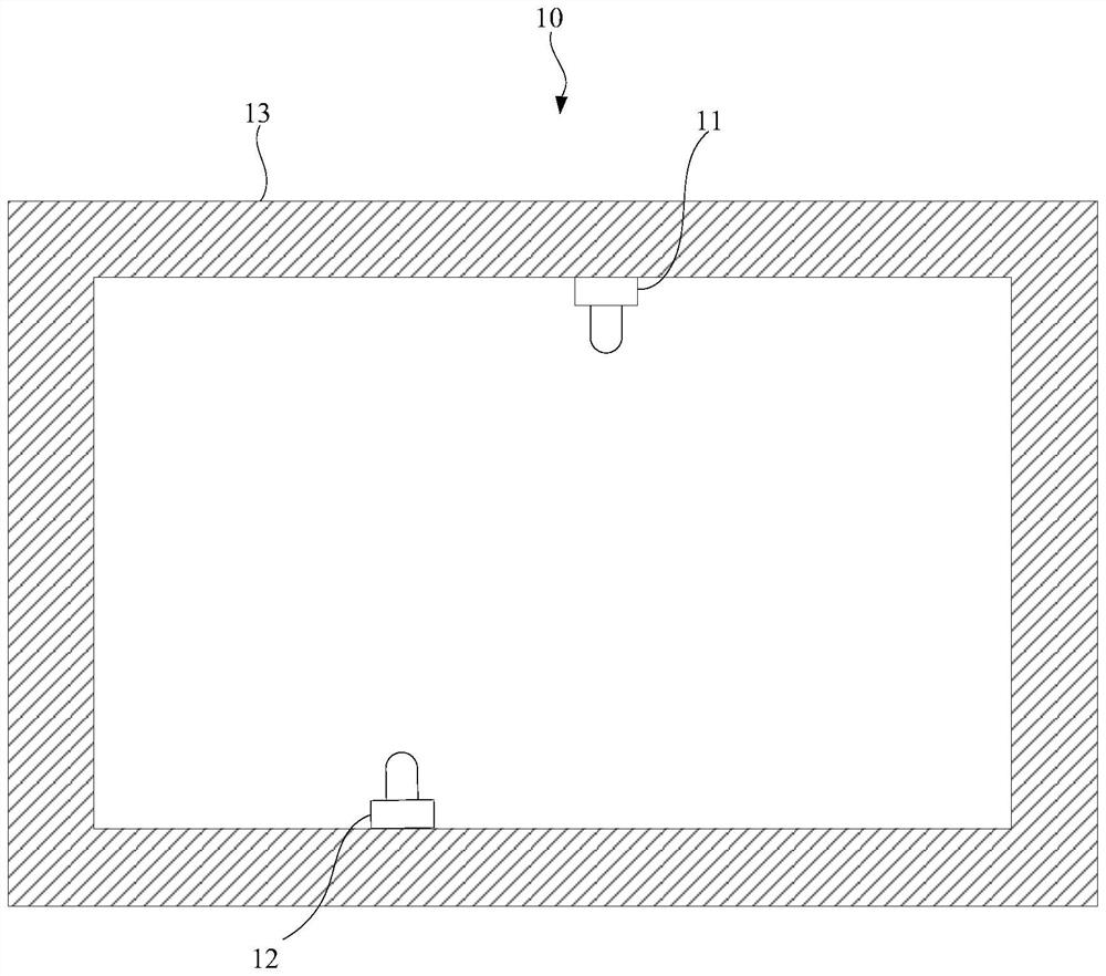
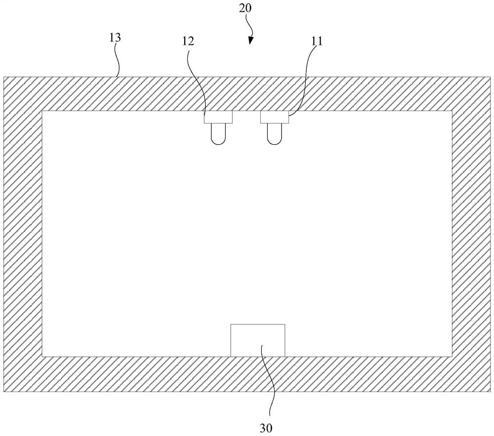
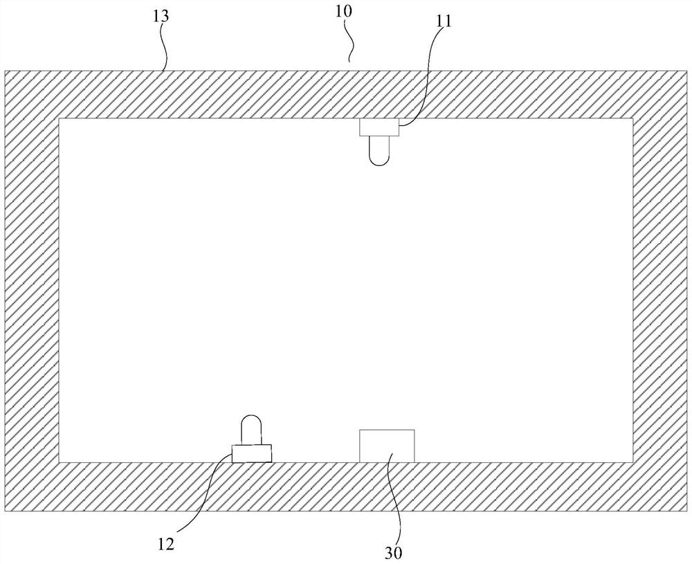

Image

  • Photoelectric detector testing device and testing method
  • Photoelectric detector testing device and testing method
  • Photoelectric detector testing device and testing method

Examples


Embodiment Construction

[0045] In order to facilitate the understanding of the present application, the present application will be described more fully below with reference to the relevant drawings. Preferred embodiments of the application are shown in the accompanying drawings. However, the present application can be embodied in many different forms and is not limited to the embodiments described herein. On the contrary, the purpose of providing these embodiments is to make the disclosure of the application more thorough and comprehensive.

[0046] Unless otherwise defined, all technical and scientific terms used herein have the same meaning as commonly understood by one of ordinary skill in the technical field to which this application belongs. The terminology used herein in the description of the application is only for the purpose of describing specific embodiments, and is not intended to limit the application.

[0047] In order to solve the current problem that the linearity test of photodete...


PUM


Abstract

The invention relates to a photoelectric detector testing device and method, and the method comprises the steps: converting a relation curve between the input optical power of a photoelectric detector and a conversion current into a relation curve between the input current of a second light source and the conversion current of the photoelectric detector, so that the linearity test of the photoelectric detector does not depend on the optical power value of the light source any more; therefore, the use of light source calibration equipment is omitted in the test process, the evaluation of the linearity of the photoelectric detector is realized under the condition that the light source calibration equipment is not used, and the cost of evaluating the linearity of the photoelectric detector is remarkably reduced. Besides, the first light source and the second light source are simultaneously arranged in the photoelectric detector testing device provided by the invention, so that the first light source shares the optical power originally required to be provided by the second light source on the premise that the light sources are utilized to provide the same illumination for the photoelectric detector; the problem that the second light source is prone to light attenuation when working at high light power is avoided, and the accuracy of linearity testing is improved.

Description

technical field [0001] The invention relates to the technical field of sensors, in particular to a photodetector testing device and testing method. Background technique [0002] Photodetectors are sensors made of materials with photoelectric effects that convert light radiation signals into electrical signals. The greater the intensity of light, the greater the photocurrent, and it is almost an insulator when there is no light. It is widely used in various fields of military and national economy: such as industrial automation, smart wear, missile guidance, light measurement and detection, flame detection, communication, etc. [0003] Linearity is an important indicator of photodetectors. At present, when testing the linearity of photodetectors, the most common method is to use special light source calibration equipment to calibrate the optical power of the light source in advance, and then test the photoelectricity under dark conditions. The output current of the detector u...

Claims


Application Information

Patent Timeline
Patent Type & Authority Applications(China)
IPC IPC(8): G01M11/00
Inventor 杨正官魏冬寒孙平如苏宏波杨丽敏
Owner SHENZHEN JUFEI OPTOELECTRONICS CO LTD
Learn More