
Laser radar chip, laser radar and laser detection method thereof

A laser radar and chip technology, which is applied in the direction of measuring devices, radio wave measurement systems, electromagnetic wave re-radiation, etc., can solve the problems of large optical loss and large laser radar chip size, and achieve the effect of reducing size and optical loss

Pending Publication Date: 2022-04-12
BEIJING WANJI TECH
View PDF0 Cites 6 Cited by
  • Summary
  • Abstract
  • Description
  • Claims
  • Application Information

AI Technical Summary

Problems solved by technology

The MZI structure needs to go through multi-level routing before the laser can be radiated into space. That is to say, a laser beam needs to go through many MZI switches and multiple routings when it is finally transmitted to space, and the large number of MZI switches will lead to The size of the lidar chip is large, and the more MZI switches the laser passes through, the greater the optical loss

Method used


Image

  • Laser radar chip, laser radar and laser detection method thereof
  • Laser radar chip, laser radar and laser detection method thereof
  • Laser radar chip, laser radar and laser detection method thereof

Examples


Embodiment Construction

[0027] In order to make the purpose, technical solutions and advantages of the present application clearer, the technical solutions in the embodiments of the present application will be described in more detail below in conjunction with the drawings in the preferred embodiments of the present application. In the drawings, the same or similar reference numerals denote the same or similar components or components having the same or similar functions throughout. The described embodiments are some, but not all, embodiments of the application. The embodiments described below by referring to the figures are exemplary, and are intended to explain the present application, and should not be construed as limiting the present application. Based on the embodiments in this application, all other embodiments obtained by persons of ordinary skill in the art without creative efforts fall within the protection scope of this application. Embodiments of the present application will be described...


PUM

PropertyMeasurementUnit
lengthaaaaaaaaaa
thicknessaaaaaaaaaa
thicknessaaaaaaaaaa

Abstract

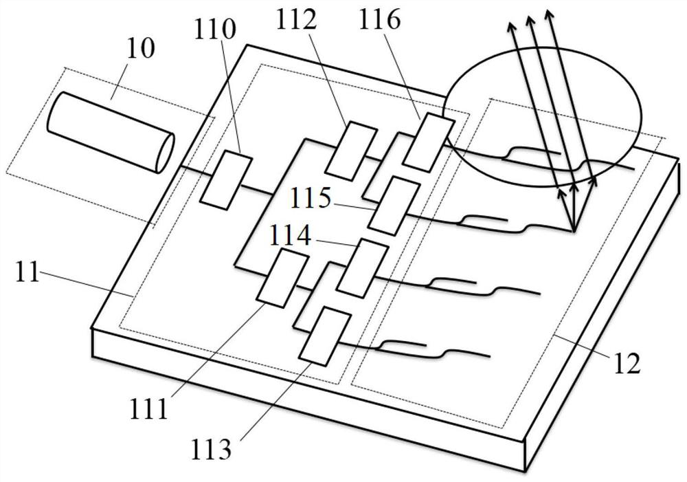
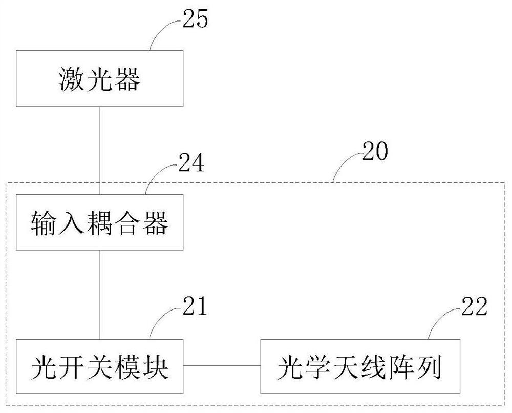
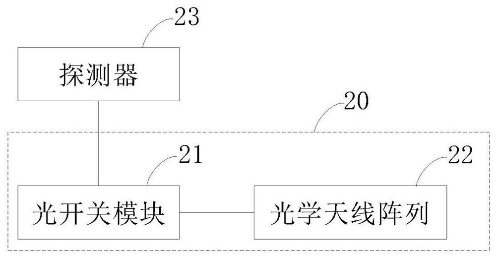
The embodiment of the invention provides a laser radar chip, a laser radar and a laser detection method thereof. The laser radar chip comprises an optical switch module and an optical antenna array which are connected with each other, the optical switch module is connected to a detector or an input coupler, and the input coupler is connected to a laser; the input coupler is used for receiving laser emitted by the laser and sending the laser to the optical switch module through the optical waveguide; the optical switch module comprises a micro-ring and an optical waveguide and is used for transmitting the laser to the optical antenna array or transmitting a reflection echo corresponding to the laser to the detector; and the optical antenna array is used for emitting the laser to a space or receiving a reflection echo corresponding to the laser and sending the reflection echo to the optical switch module. According to the embodiment of the invention, the size of the laser radar chip and the optical loss can be reduced.

Description

technical field [0001] The embodiments of the present application relate to the technical field of laser radar, and in particular to a laser radar chip, a laser radar and a laser detection method thereof. Background technique [0002] With the development of autonomous driving and remote sensing technology, lidar has received more and more attention. [0003] At present, the optical transmission of lidar is realized based on the optical switch, and the mainstream optical switch is the Mach-Zehnder interferometer (MZI) structure. The MZI structure needs to go through multi-level routing before the laser can be radiated into space. That is to say, a laser beam needs to go through many MZI switches and multiple routings when it is finally transmitted to space, and the large number of MZI switches will lead to The size of the lidar chip is large, and the more MZI switches the laser passes through, the greater the optical loss will be. Contents of the invention [0004] Embod...

Claims


Application Information

Patent Timeline
Patent Type & Authority Applications(China)
IPC IPC(8): G01S7/481G01S17/88
Inventor 王鹏飞徐洋罗光振张冶金于红艳潘教青邓永强
Owner BEIJING WANJI TECH
Learn More