Cover plate structure of flexible display module, flexible display module and flexible display equipment
A flexible display and display panel technology, applied in the direction of instruments, identification devices, etc., can solve the problems of large rebound force and large displacement of the support layer, and achieve the effects of reducing the rebound force, maintaining the fit, and reducing the probability of damage
- Summary
- Abstract
- Description
- Claims
- Application Information
AI Technical Summary
Problems solved by technology
Method used
Image
Examples
Embodiment 1
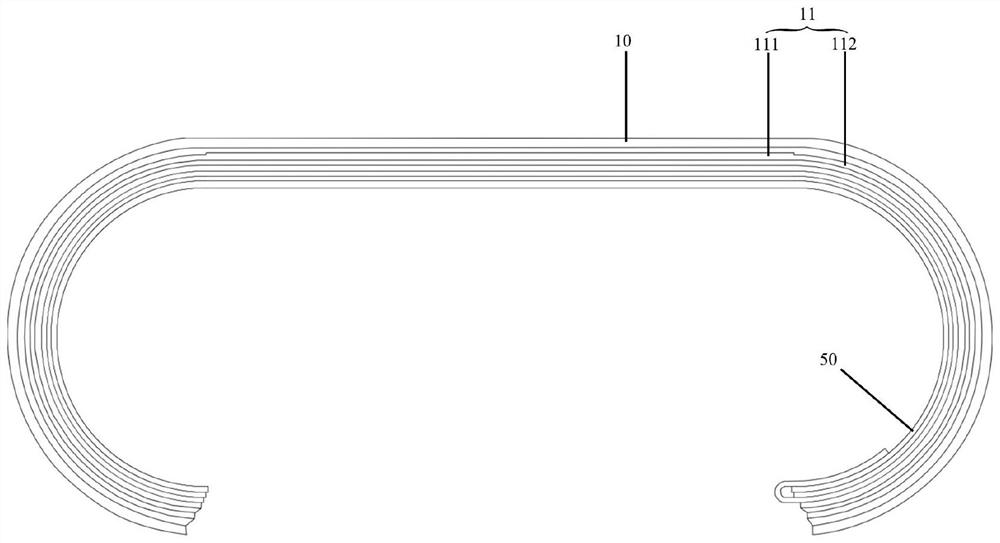
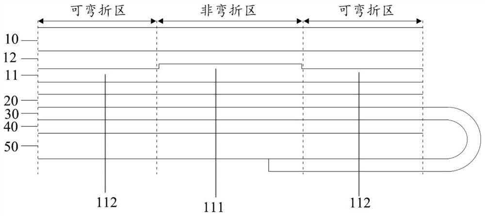
[0043] see figure 2 and image 3 The cover structure of the flexible display module provided in this embodiment is used to cover the surface of the flexible display module. On the one hand, it can provide protection for the flexible display module; Provide users with a good touch feel. The cover plate structure includes an organic cover plate layer 10 and a flexible glass layer 11 that are attached together. Specifically, the material of the organic cover layer 10 is generally polyimide (PI), and may also be polyethylene terephthalate (PET) or other organic materials. In this embodiment, the thickness of the organic cover layer 10 is 60-90 microns. The flexible glass layer 11 is bendable glass, generally ultra-thin glass (UTG). An adhesive layer 12 is generally arranged between the organic cover layer 10 and the flexible glass layer 11, and the adhesive layer 12 bonds the organic cover layer 10 and the flexible glass layer 11 together; the material of the adhesive layer 1...
Embodiment 2
[0054] Same as the above-mentioned embodiment 1, in this embodiment, the cover plate structure of the flexible display module also includes the attached organic cover plate layer 10 and the flexible glass layer 11; and the flexible glass layer 11 also includes the first part 111 and the second part 112 , the thickness of the first part 111 is greater than the thickness of the second part 112 .
[0055] Such as Figure 6 and Figure 7 As shown, in this embodiment, the side of the flexible glass layer 11 facing the organic cover layer 10 is planar and parallel to the organic cover layer 10 . The portion of the first portion 111 of the flexible glass layer 11 that is thicker than the second portion 112 protrudes from the side of the flexible glass layer 11 facing away from the organic cover layer 10 .
[0056] In this embodiment, the thickness of the first part 111 of the flexible glass layer 11 is greater than the thickness of the second part 112. Therefore, the same as the ab...
Embodiment 3
[0061] Same as the first embodiment above, in this embodiment, the cover structure of the flexible display module also includes an organic cover layer 10 and a flexible glass layer 11 that are bonded together.
[0062] Different from the above-mentioned embodiment 1 and embodiment 2, in this embodiment, as Figure 8 and Figure 9 As shown, the flexible glass layer 11 is only disposed on the area of the cover structure corresponding to the non-bending area of the flexible display module. In other words, no flexible glass layer 11 is provided in the bendable area.
[0063] In order to fill the gap in the area where the flexible glass layer 11 is not provided in the above-mentioned bendable area, a filling layer arranged on the same layer as the flexible glass layer 11 is provided in the area of the cover structure corresponding to the bendable area of the flexible display module 14 , the filling layer 14 can enable other layer structures on both sides of the flexible g...
PUM
 Abstract
Description
Claims
Application Information
 - R&D
- Intellectual Property
- Life Sciences
- Materials
- Tech Scout
- Unparalleled Data Quality
- Higher Quality Content
- 60% Fewer Hallucinations
Browse by: Latest US Patents, China's latest patents, Technical Efficacy Thesaurus, Application Domain, Technology Topic, Popular Technical Reports.
© 2025 PatSnap. All rights reserved.Legal|Privacy policy|Modern Slavery Act Transparency Statement|Sitemap|About US| Contact US: help@patsnap.com


