Dead zone compensation circuit, driving circuit, method and chip

A dead-time compensation and drive circuit technology, applied in electrical components, output power conversion devices, etc., can solve problems affecting the performance of driven equipment, distortion, current compression, etc., to achieve precise control of load action, prevent compression and distortion. , the effect of current smoothing

Pending Publication Date: 2022-04-12
深圳率能半导体有限公司
View PDF0 Cites 0 Cited by
  • Summary
  • Abstract
  • Description
  • Claims
  • Application Information

AI Technical Summary

Problems solved by technology

[0002] In the existing driving device, since the full-bridge circuit has a dead zone during operation, that is, when the current is positive, the current flows from the chip through the full-bridge circuit to the load connected to the full-bridge circuit, and the voltage on the load line The high-level time is less than the target time by one dead time, on the contrary, the low-level time of the voltage on the load line is longer than the target time by one dead time, resulting in compression and distortion of the current output by the drive device, Thus affecting the performance of the driven equipment

Method used


Image

  • Dead zone compensation circuit, driving circuit, method and chip
  • Dead zone compensation circuit, driving circuit, method and chip
  • Dead zone compensation circuit, driving circuit, method and chip

Examples


Embodiment Construction

[0039] The technical solutions in the embodiments of the present application will be clearly and completely described below in conjunction with the drawings in the embodiments of the present application. Apparently, the described embodiments are only some of the embodiments of this application, not all of them. Based on the embodiments in this application, all other embodiments obtained by those skilled in the art without making creative efforts belong to the scope of protection of this application.

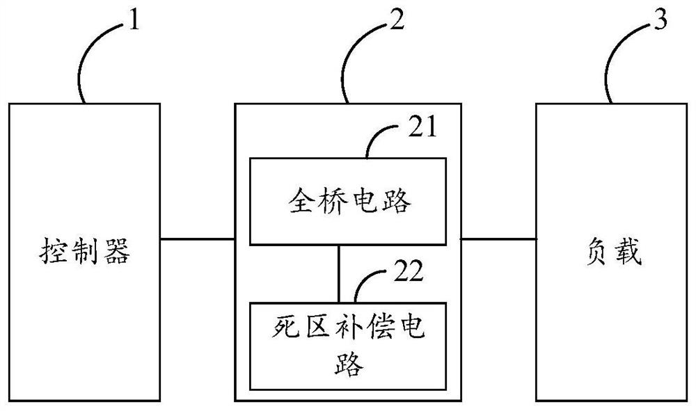
[0040] It should be noted that most of the existing full-bridge circuits are composed of two half-bridge circuits (upper half-bridge and lower half-bridge), and when the device is driven, since the upper and lower half-bridges are turned on alternately, a dead zone is generated, while The existence of the dead zone will lead to current compression and distortion, thereby affecting the performance of the driven equipment.

[0041] In order to solve the above problems, the embodim...


PUM


Abstract

The invention discloses a dead zone compensation circuit, a driving circuit, a method and a chip, and relates to the technical field of control driving, and the dead zone compensation circuit comprises a zero-crossing detection unit which is used for detecting a zero-crossing signal and sending the zero-crossing signal to a signal detection unit; the signal detection unit is connected with the zero-crossing detection unit and used for receiving the zero-crossing signal, determining a signal to be compensated according to the zero-crossing signal and sending the signal to be compensated to the signal compensation unit; and the signal compensation unit is connected with the signal detection unit and is used for receiving the signal to be compensated and adjusting the dead time according to the signal to be compensated. The circuit dead zone is compensated, so that the output current of the driving circuit is smoother, and the output current of the driving circuit is prevented from being compressed and distorted.

Description

technical field [0001] The present application relates to the technical field of control driving, and in particular to a dead zone compensation circuit, a driving circuit, a method and a chip. Background technique [0002] In the existing driving device, since the full-bridge circuit has a dead zone during operation, that is, when the current is positive, the current flows from the chip through the full-bridge circuit to the load connected to the full-bridge circuit, and the voltage on the load line The high-level time is less than the target time by one dead time, on the contrary, the low-level time of the voltage on the load line is longer than the target time by one dead time, resulting in compression and distortion of the current output by the drive device, Thus affecting the performance of the driven equipment. Contents of the invention [0003] In view of this, the embodiments of the present application provide a dead zone compensation circuit, a driving circuit, a ...

Claims


Application Information

Patent Timeline
IPC IPC(8): H02M1/38H02M1/088H02M1/08
Inventor 谢永亮杜如峰陈靖文黄涛涛林鸿武
Owner 深圳率能半导体有限公司
Why Eureka
Try Eureka