Solar photovoltaic fence for oil well

A solar photovoltaic and oil well technology, applied in the direction of solar thermal energy, solar thermal power generation, solar collectors, etc., can solve the problems of photovoltaic panel damage, photovoltaic fence support bending, photovoltaic fence damage, etc., and achieve the effect of avoiding excessive wind speed

Active Publication Date: 2022-04-12
胜利油田大源节能设备有限公司
View PDF12 Cites 2 Cited by
  • Summary
  • Abstract
  • Description
  • Claims
  • Application Information

AI Technical Summary

Problems solved by technology

[0004] In order to overcome the shortcoming that when encountering strong winds, the support of the photovoltaic fence is bent due to the fast wind speed hitting the photovoltaic fence, which damages the photovoltaic fence. , the invention provides a solar photovoltaic fence for oil wells

Method used


Image

  • Solar photovoltaic fence for oil well
  • Solar photovoltaic fence for oil well
  • Solar photovoltaic fence for oil well

Examples


Embodiment 1

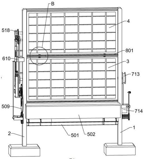
[0035] A kind of solar photovoltaic fence for oil well, such as Figure 1-Figure 15 As shown, it includes a first mounting frame 1, a second mounting frame 2, a first photovoltaic panel 3, a second photovoltaic panel 4, a turning mechanism, a fixing mechanism and a reset mechanism, and the second mounting frame 2 is set on the first mounting frame 1 On the left side, the first mounting frame 1 and the second mounting frame 2 are vertically arranged, and the first mounting frame 1 and the second mounting frame 2 are connected with the first photovoltaic panel 3 and the second photovoltaic panel 4 through the rotating shaft rotation inside, The first photovoltaic panel 3 and the second photovoltaic panel 4 are vertically arranged, and the shafts on the left and right sides of the first photovoltaic panel 3 and the second photovoltaic panel 4 pass through the first mounting frame 1 and the second mounting frame 2, and the second The photovoltaic panel 4 is located on the upper si...

Embodiment 2

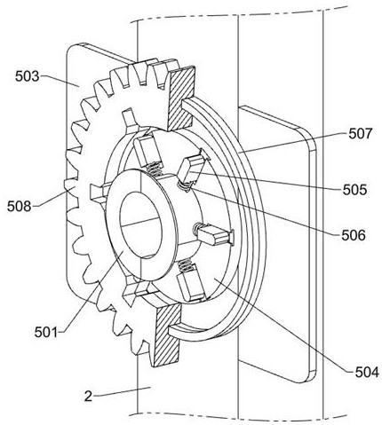
[0038] On the basis of Example 1, such as Figure 1-Figure 8 As shown, the turning mechanism includes a power assembly, a power cut-off assembly, a first fixed frame 512, a fixed shaft 512a, a first synchronous pulley 513, a second synchronous pulley 514, a third synchronous pulley 515, a fourth gear 516, The fifth gear 517, the limit fixed block 518, the first sliding rod 519 and the first spring 520, the power assembly is located at the lower part between the inner side of the first installation frame 1 and the second installation frame 2, and the power assembly is located at the first photovoltaic panel 3, the power cut-off assembly is located at the lower part of the left side of the second installation frame 2, the power cut-off assembly is mechanically matched with the power assembly, the first fixing frame 512 is fixedly connected to the lower part of the rear side of the second installation frame 2, and the first fixing A fixed shaft 512a is rotatably connected to the ...

Embodiment 3

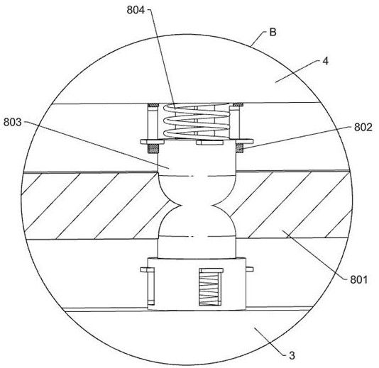
[0050] On the basis of Example 2, such as Figure 16 As shown, it also includes a limit mechanism. The limit mechanism includes a limit fixing plate 801, a fixed seat 802, a fourth sliding rod 803 and a seventh spring 804. The limit fixing plate 801 is fixed on the first mounting frame 1 and the second Between the inner sides of the mounting frame 2, the upper, lower, left and right sides of the limit fixing plate 801 are provided with circular holes, and the upper side of the first photovoltaic panel 3 and the lower side of the second photovoltaic panel 4 are fixedly connected with fixed holes. Seat 802, the fourth sliding rod 803 is slidably connected in the fixed seat 802, the inner end of the fourth sliding rod 803 is set as a semicircular ball, the middle part of the fixed seat 802 is provided with a seventh spring 804, and the two ends of the seventh spring 804 are fixed on Adjacent to the fixing seat 802 and the fourth sliding rod 803 , the inner end of the fourth slidi...


PUM


Abstract

The invention relates to the field of photovoltaic power generation fences, in particular to a solar photovoltaic fence for an oil well. The technical problems that impact force generated by strong wind acts on a photovoltaic panel, a photovoltaic fence support is bent, a photovoltaic fence is damaged, and meanwhile due to the fact that the wind speed is too high and impurities such as sand and stone particles impact the photovoltaic panel, the photovoltaic panel is damaged and cannot be used normally are solved. According to the technical scheme, the solar photovoltaic fence for the oil well comprises a first mounting frame, a second mounting frame and a turnover mechanism, the second mounting frame is arranged on the left side of the first mounting frame, the first mounting frame and the second mounting frame are vertically arranged, and the turnover mechanism is arranged on the left side of the second mounting frame. According to the invention, through the arrangement of the turnover mechanism, wind rapidly passes through the space between the first photovoltaic panel and the second photovoltaic panel, the impact force area of the wind on the first photovoltaic panel and the second photovoltaic panel is reduced, and the damage caused by the bending of the first mounting rack and the second mounting rack is avoided.

Description

technical field [0001] The invention relates to the field of photovoltaic power generation fences, in particular to a solar photovoltaic fence for oil wells. Background technique [0002] At present, the pumping wells mostly use conventional power grids to power the pumping wells, and remote single wells need to erect additional power lines, which increases production costs; on the other hand, in order to protect the safety of the pumping well equipment, it is necessary to build fences around the pumping wells It has no other functions except the protective effect, and the investment cost is high, and the utilization benefit is low. With the development of photovoltaic module technology, photovoltaic fences are also gradually applied; photovoltaic fences use photovoltaic panels that generate electricity on both sides, and the photovoltaic panels on the back rely on natural ground reflection light to generate electricity, so as to maximize the conversion of solar energy into ...

Claims


Application Information

Patent Timeline
Patent Type & Authority Applications(China)
IPC IPC(8): H02S20/30F24S30/425E04H17/14
CPCY02E10/50Y02E10/47
Inventor 吴兆君
Owner 胜利油田大源节能设备有限公司
Why Eureka
Try Eureka