Intelligent monitoring system for green building

A technology of intelligent monitoring system and green building, applied in color TV parts, TV system parts, cleaning methods using tools, etc., can solve the problem of low maintenance efficiency, inability to protect infrared imaging cameras, and easy to leave behind. Stains and other problems, to achieve the effect of improving practicability

Inactive Publication Date: 2022-04-12
LINYI UNIVERSITY +1
View PDF0 Cites 1 Cited by
  • Summary
  • Abstract
  • Description
  • Claims
  • Application Information

AI Technical Summary

Problems solved by technology

[0007] The purpose of the present invention is to provide an intelligent temperature distribution monitoring system for green buildings, to solve the problem that the current intelligent monitoring system proposed in the above background technology adopts a drive motor to drive the rotation of the infrared imaging camera, and The driving motor is generally integrated with the infrared imaging camera. Therefore, when the driving motor fails, the infrared imaging camera needs to be completely disassembled for maintenance. The efficiency of maintenance is low. The current intelligent monitoring system cannot protect the infrared imaging camera well when the infrared imaging camera is dormant, which will cause the infrared imaging camera to be exposed for a long time. Under the long-term interference of some mosquitoes, the It is easy to leave stains, so it will cause the shooting of the infrared imaging camera to be unclear, etc. At present, the thermal imaging monitoring technology of the infrared imaging camera is mainly used in the warehouse of some flammable and explosive products, or the monitoring of human body temperature, which cannot realize the green Problems in building indoor temperature distribution monitoring and image data collection

Method used


Image

  • Intelligent monitoring system for green building
  • Intelligent monitoring system for green building
  • Intelligent monitoring system for green building

Examples


Embodiment Construction

[0033] The following will clearly and completely describe the technical solutions in the embodiments of the present invention with reference to the accompanying drawings in the embodiments of the present invention. Obviously, the described embodiments are only some, not all, embodiments of the present invention. Based on the embodiments of the present invention, all other embodiments obtained by persons of ordinary skill in the art without making creative efforts belong to the protection scope of the present invention.

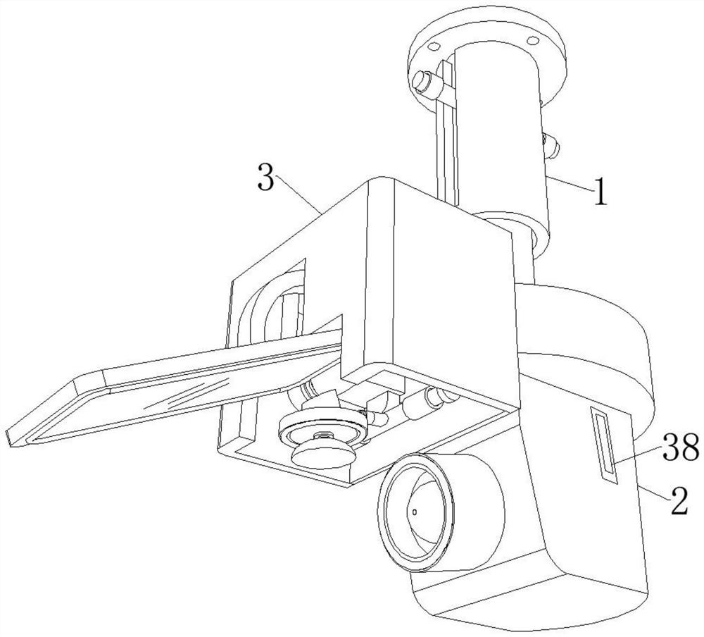
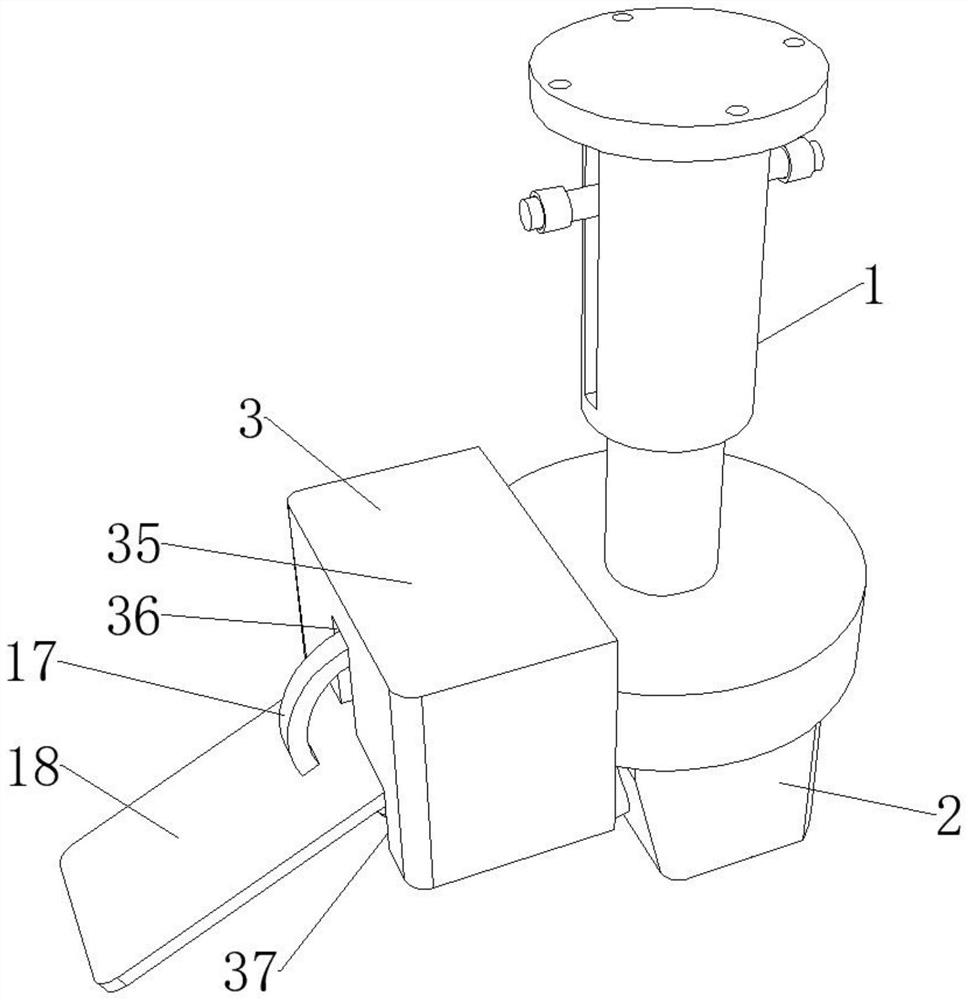
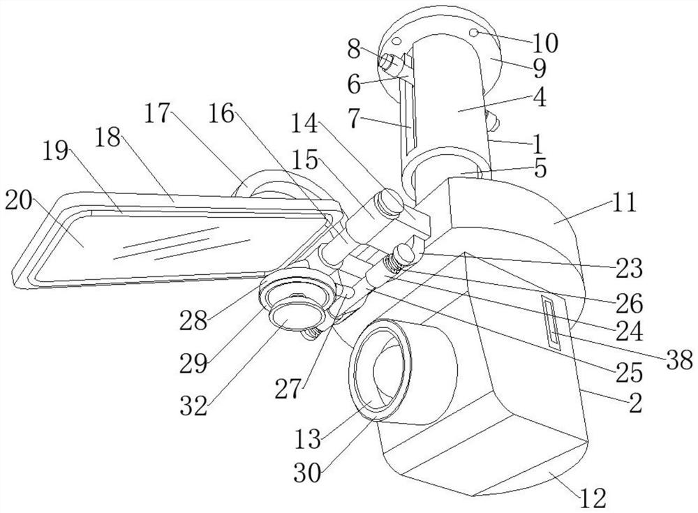
[0034] see Figure 1-8 , the present invention provides an intelligent monitoring system for green buildings, including an installation part 1, a thermal imaging monitoring device 2, an adjustment device 3 and a data storage module 38, the installation part 1 includes a storage tube 4, and the storage tube 4 is slidingly arranged with Lifting rod 5;

[0035] The thermal imaging monitoring device 2 includes a connecting plate 11, a control box 12 is installed ...


PUM


Abstract

The invention discloses an intelligent temperature distribution monitoring system for a green building, and relates to the technical field of infrared thermal imaging, the intelligent temperature distribution monitoring system comprises a mounting part, a thermal imaging monitoring device and an adjusting device, the mounting part comprises a storage cylinder, and a lifting rod is slidably arranged in the storage cylinder. Through mutual cooperation of a transverse plate, a positioning sleeve, a rotating rod, an arc-shaped rod, a long strip plate, a convex strip, a lens and a forward and reverse motor, when an output shaft of the forward and reverse motor drives the rotating rod to rotate, the arc-shaped rod rotates to drive the long strip plate to rotate with the rotating rod as the axis, and the inclination angle of the long strip plate can be adjusted; when the left side of the long-strip-shaped plate inclines downwards by a certain angle, the lens on the bottom side of the long-strip-shaped plate can just correspond to the opposite direction right opposite to the infrared imaging camera, then the infrared imaging camera can shoot the area which is not covered by the rear side through the lens, and then shooting of the area which is not covered by the infrared imaging camera is achieved. And the infrared imaging camera does not need to rotate and the like.

Description

technical field [0001] The invention relates to a temperature monitoring system, in particular to a monitoring system for intelligent temperature distribution changes in green buildings. Background technique [0002] The evaluation of green buildings should follow the principle of adapting measures to local conditions, and consider the characteristics of the climate, environment, resources, economy and culture of the area where the building is located. Comprehensive evaluation of indicators and other performance; the indoor layout of green buildings is very reasonable, minimize the use of synthetic materials, make full use of sunlight, save energy, create a feeling close to nature for residents, and focus on the coordinated development of people, buildings and the natural environment. The goal is to control and reduce the use and damage of the natural environment as much as possible while using natural conditions and artificial means to create a good and healthy living envir...

Claims


Application Information

Patent Timeline
Patent Type & Authority Applications(China)
IPC IPC(8): H04N5/225H04N5/33G01J5/48F16J15/02F16M11/04F16M11/10F16M11/18F16M13/02B08B1/04G01J5/00
Inventor 宋静
Owner LINYI UNIVERSITY
Why Eureka
Try Eureka