
Intervertebral space maintaining distraction device for lumbar anterior surgery

A technology for intervertebral space and surgery, applied in the field of medical devices, can solve the problems of difficult to clearly see the back of the intervertebral space, narrow space of the intervertebral space, long passage, etc., to improve convenience and efficiency, and ensure accuracy. Effect

Pending Publication Date: 2022-04-15
FUJIAN PROVINCIAL HOSPITAL
View PDF0 Cites 0 Cited by
  • Summary
  • Abstract
  • Description
  • Claims
  • Application Information

AI Technical Summary

Problems solved by technology

[0003] Due to the small surgical incision, long channel, and deep anatomical position of the OLDF operation, there is a surgical blind spot in the removal of the intervertebral disc tissue at the posterior edge of the vertebral body at this time, and the target area can only be reached by feeling, and the intervertebral disc cannot be cleaned very often. , especially for some patients with severe lumbar degeneration and significantly decreased intervertebral height, the intervertebral space is narrow, and it is more difficult to deal with the intervertebral disc and endplate, and it is difficult to clearly see the back of the intervertebral space. To perform distraction and maintenance, and to give the rear enough space for operation, a device for maintaining intervertebral space distraction for anterior lumbar surgery came into being

Method used


Image

  • Intervertebral space maintaining distraction device for lumbar anterior surgery
  • Intervertebral space maintaining distraction device for lumbar anterior surgery
  • Intervertebral space maintaining distraction device for lumbar anterior surgery

Examples


Embodiment Construction

[0025] The following is further described in detail through specific implementation methods:

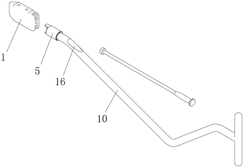
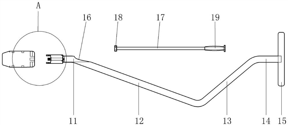
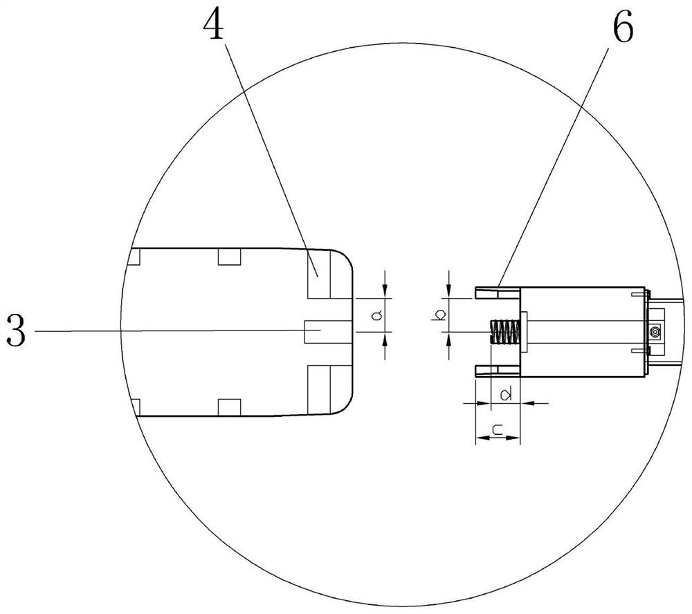
[0026] The reference signs in the drawings of the description include: expansion block 1, wedge portion 2, threaded hole 3, positioning cavity 4, sleeve 5, positioning block 6, rotating shaft 7, first stop 8, second stop 9, Connecting rod 10, first horizontal section 11, first inclined section 12, second inclined section 13, second horizontal section 14, handle 15, opening 16, rotating rod 17, sleeve cap 18, handle 19.

[0027] Example figure 1 As shown, a device for maintaining intervertebral space distraction for anterior lumbar surgery includes a distraction block 1 whose shape and structure are imitated according to the structure of the intervertebral space of the human body. The distraction block 1 in this embodiment is made of aluminum It is made of magnesium alloy, and contains two metal needles inside, which is convenient for perspective positioning during the operation. The...


PUM


Abstract

The invention belongs to the technical field of medical instruments, and particularly discloses an intervertebral space maintaining distraction device for an anterior lumbar surgery, which comprises a distraction block, a threaded hole formed in one end of the distraction block and a positioning cavity adjacent to the threaded hole, and further comprises a sleeve, a positioning block matched with the positioning cavity is arranged at one end of the sleeve, and a rotating shaft is sleeved with the sleeve; a first check block is arranged on the rotating shaft and located on one side of the positioning block, a second check block is detachably connected to the other side of the rotating shaft, and one end, located on the first check block, of the rotating shaft can be in threaded connection with the threaded hole; the connecting rod is coaxially and detachably connected with the end, away from the positioning block, of the sleeve; an opening is formed in the end, close to the sleeve, of the connecting rod in the axial direction of the sleeve; and one end of the rotating rod is connected with a sleeve cap which can be buckled with the second check block. According to the scheme, a brand-new surgical instrument is constructed on the basis of an OLDF operation, and is mainly applied to oblique lateral lumbar intervertebral disc resection and fusion and used for maintaining intervertebral space distraction.

Description

technical field [0001] The invention belongs to the technical field of medical devices, and specifically discloses a device for maintaining intervertebral space for lumbar anterior surgery. Background technique [0002] Oblique Lateral Lumbar Interbody Fusion (OLIF) has been widely used in various degenerative lumbar diseases since it was officially proposed in 2012. In this operation, the working channel is placed through the natural gap between the left psoas major muscle and the anterior great vessel sheath, and the surgical treatment is completed from the oblique lateral approach. A larger intervertebral fusion device is placed to expand the intervertebral space to reach the spinal canal And the indirect decompression effect of the intervertebral foramen, the purpose of restoring the intervertebral height. Nowadays, most scholars believe that because OLIF is not suitable for direct decompression, the indications for severe spinal stenosis or combined disc herniation are...

Claims


Application Information

Patent Timeline
Patent Type & Authority Applications(China)
IPC IPC(8): A61B17/02A61B17/88
Inventor 徐杰宋超林院郑武肖毓华郑益新俞云龙田建平
Owner FUJIAN PROVINCIAL HOSPITAL
Learn More