Micro-current foot massage insole and manufacturing method thereof

A technology of micro-current and insoles, applied in insoles, footwear, clothing, etc., can solve the problems of penetrating acupoints, achieve the effects of reducing high blood pressure, promoting blood circulation throughout the body, and improving blood circulation in the body

Pending Publication Date: 2022-04-15
姜籽宇
View PDF5 Cites 0 Cited by
  • Summary
  • Abstract
  • Description
  • Claims
  • Application Information

AI Technical Summary

Problems solved by technology

Now people have higher and higher health requirements, and sometimes people will relieve fatigue by massaging the soles of the feet, but the foot massage devices on the market are only used in acupressure, etc. massage

Method used


Image

  • Micro-current foot massage insole and manufacturing method thereof
  • Micro-current foot massage insole and manufacturing method thereof
  • Micro-current foot massage insole and manufacturing method thereof

Examples


Embodiment 1

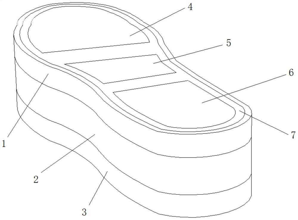
[0044] Embodiment one: refer to figure 1 , figure 2 , Figure 5 , Image 6 , Figure 7 , the invention discloses a micro-current foot massage insole, which includes an insole body, a pulse device, a heating device, a control chip, a communication device, a power supply device, and a remote control device. The pulse device and the heating device are electrically connected to the control chip, The control chip is communicatively connected with the remote control device through the communication device, and the pulse device is a micro-current pulse contact sheet.

[0045] The insole body includes an upper surface layer, a middle layer and a bottom layer, and the upper surface layer, the middle layer and the bottom layer are detachably connected. Specifically, the upper surface layer, the middle layer and the bottom layer are connected by Velcro. The detachable connection between the upper surface layer, the middle layer and the bottom layer can facilitate the replacement of ...

Embodiment 2

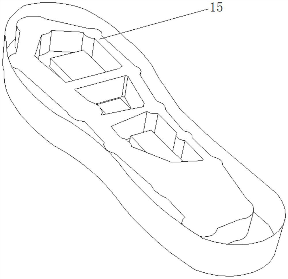
[0049] Embodiment two: refer to figure 1 , image 3 , Figure 5 , Image 6 , Figure 7 , the difference from Embodiment 1 is that the middle layer is provided with an air cushion device. The air cushion device includes an air bag, and the air bag is provided with an air port and an air valve. The air cushion device can provide good supporting force and buffering force, and has the effect of buffering and shock absorbing, and the lower surface of the bottom layer is provided with an anti-slip device. The anti-slip device is an anti-slip felt or an anti-slip pattern, and the anti-slip pattern is wavy or zigzag.

Embodiment 3

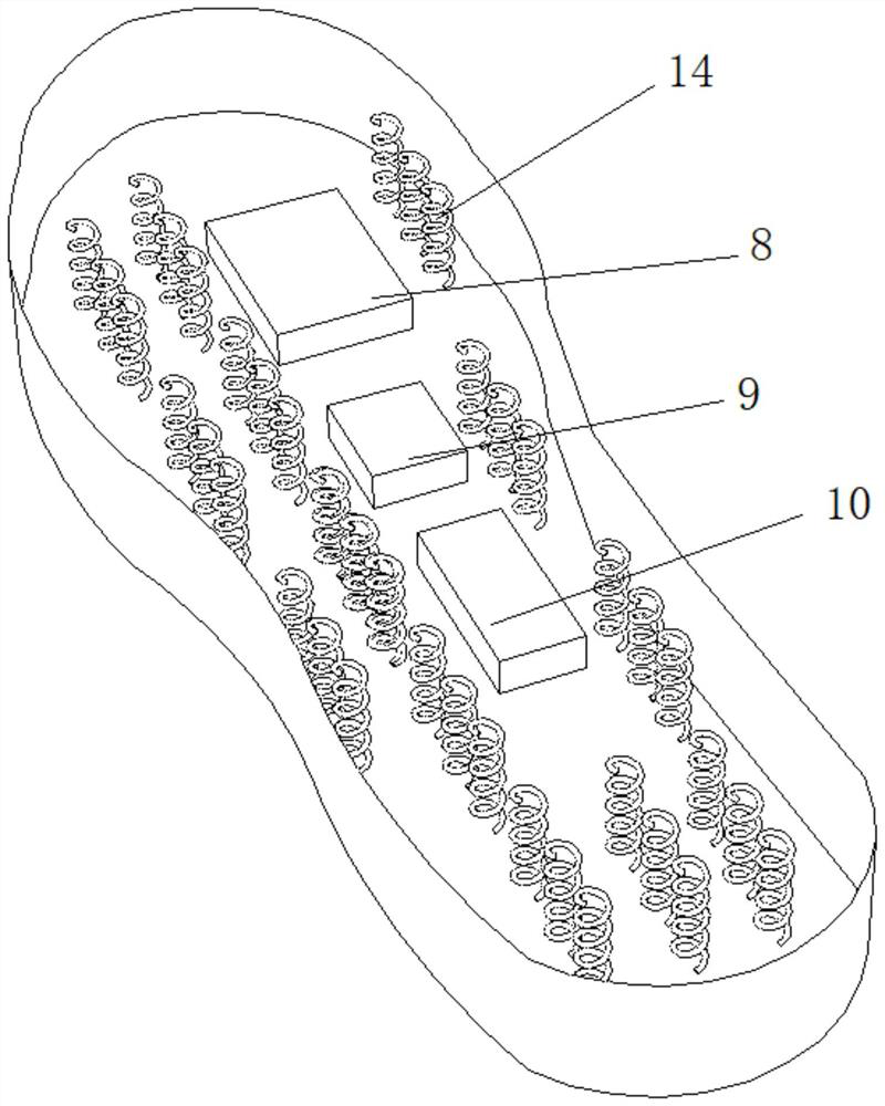
[0050] Embodiment three: refer to figure 1 , figure 2 , Figure 4 , Image 6 , Figure 7 , the difference from Embodiment 1 is that the middle layer is provided with a spring device. The spring device includes several damping springs, the upper and lower ends of the damping springs are respectively welded with metal sheets, the damping springs are cylindrical springs or conical springs, and the end of the conical springs with a larger diameter is welded on the bottom On the metal sheet, one end of the small diameter of the conical spring is welded on the upper metal sheet. The lower surface of the bottom layer is provided with a raising device. The thickness of the height-increasing device increases sequentially from front to back, and a cavity is arranged inside the height-increasing device, and the cavity is filled with polyurethane PU foam.


PUM


Abstract

The invention relates to a micro-current foot massage insole and a manufacturing method thereof. A micro-current foot massage insole comprises an insole body, a pulse device, a heating device, a control chip, a communication device, a power supply device and a remote control device, the pulse device is a micro-current pulse contact piece, and the insole body comprises an upper surface layer, a middle layer and a bottom layer. The upper surface layer comprises a first massage area, a second massage area, a third massage area and a fourth massage area, pulse devices are arranged in the first massage area, the second massage area and the third massage area, and a heating device is arranged in the fourth massage area. According to the micro-current foot massage insole and the manufacturing method thereof, the nerve acupoints of the foot can be stimulated, and the better massage effect is achieved.

Description

technical field [0001] The invention relates to the field of insoles, in particular to a microcurrent foot massage insole and a manufacturing method thereof. Background technique [0002] Feet are the second brain of the human body. When foot numbness or foot pain occurs, we cannot ignore it, because foot health is closely related to physical health. To understand the health of the body, you can often learn a thing or two through the pain in the feet. There are many acupuncture points on the feet, which have the meaning of promoting qi and blood and promoting internal and external circulation. Now people have higher and higher health requirements, and sometimes people will relieve fatigue by massaging the soles of the feet, but the foot massage devices on the market are only used in acupressure, etc. massage. [0003] The purpose of the present invention is to solve the above-mentioned problems in the prior art, and provide a micro-current insole that can directly act on ...

Claims


Application Information

Patent Timeline
Patent Type & Authority Applications(China)
IPC IPC(8): A61H39/04A61N1/36A61H39/00A61H39/06A61F7/00A43B17/02A43B17/03A43B17/08
Inventor 姜籽宇
Owner 姜籽宇
Why Eureka
Try Eureka