Chip frequency screening and subpackaging device

A sub-packaging and chip technology, applied in sorting and other directions, to meet the effect of mass production

Pending Publication Date: 2022-04-15
佛山市南海区鑫来智能电子有限公司
View PDF0 Cites 0 Cited by
  • Summary
  • Abstract
  • Description
  • Claims
  • Application Information

AI Technical Summary

Problems solved by technology

[0003] The purpose of the present invention is to provide a chip frequency screening and packaging device to solve one or more technical problems in the prior art, at least provide a beneficial option or create conditions

Method used


Image

  • Chip frequency screening and subpackaging device
  • Chip frequency screening and subpackaging device
  • Chip frequency screening and subpackaging device

Examples


Embodiment 1

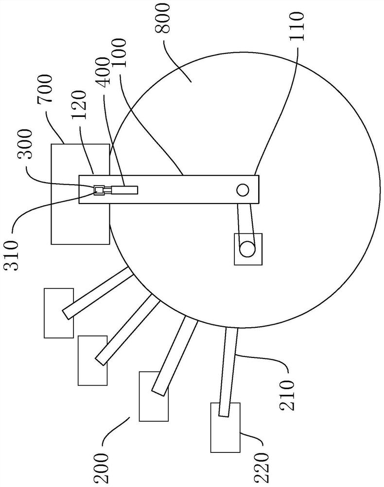
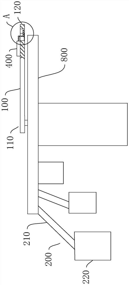
[0033] Such as Figure 1 to Figure 3 As shown, the chip frequency screening and packaging device of this embodiment includes: a packaging and rotating mechanism and a plurality of packaging and receiving mechanisms 200, wherein the packaging and rotating mechanism includes a frame 800, a turret 100, and a rotating drive assembly. The frame 100 is horizontally provided with a connection end 110 and a free end 120, the connection end 110 is rotatably connected to the frame 800, and the rotation drive assembly is in transmission connection with the connection end 110, specifically: the rotation drive assembly includes a rotation motor and a control The rotating motor is connected to the rotating shaft provided on the connecting end 110 through a transmission belt transmission structure, and the frame 800 is connected to the frame 800 through the rotating shaft, and the free end 120 is provided with a clamping device for clamping and releasing chips. structure, on the rotation pat...

Embodiment 2

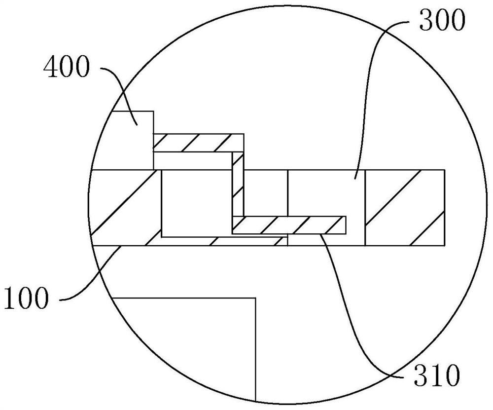
[0040] Such as Figure 4 and Figure 5 As shown, the difference between this embodiment and Embodiment 1 lies in the difference in the clamping structure. The clamping structure includes a detection material hole 300 penetrating up and down and a jacking assembly, and a stopper is arranged in the bottom of the detection material hole 300 310, the stopper 310 is an elastic member, one side of the stopper 310 is fixedly connected to the inner wall of the detection material hole 300, and the ejector assembly is provided with a push rod 500 arranged above the detection material hole 300, for The ejector drive unit drives the ejector pin 500 to move up and down, the ejector drive unit makes the lower end of the ejector pin 500 protrude into the detection material hole 300, and the chip is supported by the stopper 310 of the elastic member in this embodiment , which is equivalent to that the stopper 310 can hold the chip in the detection material hole 300, and follow the rotation o...


PUM


Abstract

The invention discloses a chip frequency screening and sub-packaging device which comprises a sub-packaging rotating mechanism and a plurality of sub-packaging material receiving mechanisms, the sub-packaging rotating mechanism comprises a rotating frame and a rotating driving assembly, and a clamping structure used for clamping and releasing chips is arranged at the free end of the rotating frame; the rotating driving assembly is used for driving the rotating frame to rotate around a vertical rotating axis, and a feeding station, a detecting station and a plurality of split charging and receiving stations are arranged on a rotating path of the clamping structure; the split charging feeding ends of the split charging and receiving mechanisms correspond to the split charging and receiving stations in a one-to-one mode. An external chip feeding device conveys a chip to a clamping structure, the clamping structure clamps the chip, the clamping structure rotates to a detection station and detects the chip, according to a detection result, the clamping structure rotates to a corresponding split charging and receiving station, then the clamping structure releases the chip, the chip is recycled to a split charging and receiving mechanism from a split charging feeding end, and the split charging and receiving mechanism is started. The chips are automatically conveyed and classified, and large-batch production is met.

Description

technical field [0001] The invention relates to the field of chip production, in particular to a chip frequency screening and packaging device. Background technique [0002] During the manufacturing process of the chip, it is necessary to perform chip detection. The chip needs to pass through a specific frequency detection device, and the corresponding frequency is sent to the chip through the frequency detection device. sort. The existing technology is to detect and classify the chips manually. The chips after inspection are simple and cumbersome, and manual errors are easy to occur. Many chips that leave the factory are often unqualified. At the same time, manual packaging is efficient. Low, not suitable for mass production. Contents of the invention [0003] The purpose of the present invention is to provide a chip frequency screening and packaging device to solve one or more technical problems in the prior art, and at least provide a beneficial option or create condi...

Claims


Application Information

Patent Timeline
IPC IPC(8): B07C5/344B07C5/02B07C5/36B07C5/38
Inventor 何德驹林宇强
Owner 佛山市南海区鑫来智能电子有限公司
Why Eureka
Try Eureka