Granule counting machine

A technology of counting machine and body, applied in the field of counting machine, can solve the problems of reducing conveying efficiency and detection accuracy, affecting material conveying efficiency, reducing detection accuracy, etc., to improve automatic classification and detection function, improve conveying efficiency, The effect of enhancing detection accuracy and efficiency

Pending Publication Date: 2022-04-15
博世勒自动化科技(昆山)有限公司
View PDF9 Cites 0 Cited by
  • Summary
  • Abstract
  • Description
  • Claims
  • Application Information

AI Technical Summary

Problems solved by technology

[0004] The object of the present invention is to provide a kind of grain counting machine, in order to solve the problem mentioned above in the background technology that the amount of material is large, and it is easy to stick to each other when conveying, which affects the conveying efficiency of the material and reduces the accuracy of detection, and the material is prone to produce a large amount of vibration during conveying. There is a lot of dust, which is prone to blockage when conveying materials of different sizes, and it is not easy to automatically classify materials of different sizes, which reduces the problem of conveying efficiency and detection accuracy

Method used


Image

  • Granule counting machine
  • Granule counting machine
  • Granule counting machine

Examples


Embodiment 1

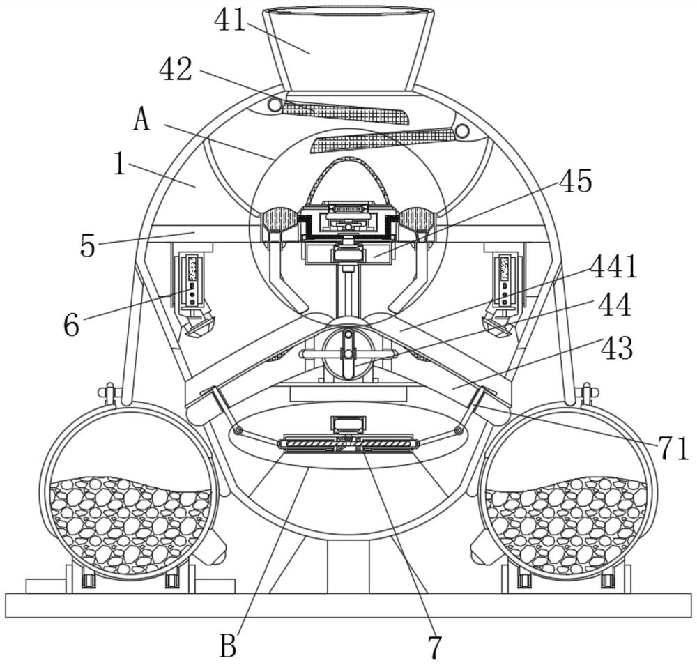
[0044] Example 1, such as Figure 1-3 As shown, while the material is guided through the classification feeding system 45 for secondary guidance, the dust can be prevented from spreading through the annular dust suction chamber outside the annular guide groove 453, and the material can be accurately slid in under the structural guidance of the cavity. The inside of the annular guide groove 453, at this time, the suction fan 457 can be activated to suck the dust into the storage groove completely through the guide tube under the filtration of the conical filter seat 451, which is convenient for the operator to carry out subsequent cleaning operations and avoids material clogging .

Embodiment 2

[0045] Example 2, such as figure 2 and Figure 5 As shown, when the two groups of material receiving seats 2 are full of materials, the start of the servo motor 77 can drive the second bevel gear set 74 to engage in the structure and force the two-way screw rod 73 to rotate, and the rotation of the two-way screw rod 73 will prompt the two groups of materials The threaded pipes 75 move away from each other, so that the internal threaded pipe 75 drives the hinged connecting rod 76 to raise the baffle 71, so that the baffle 71 erects a blocking structure on the conveying edge of the inclined material guide plate 441, and at this time, the particles can be temporarily The material is blocked, and the receiving seat 2 can be replaced during the period, and the monitoring of the infrared spectrum detector 6 is not stopped, so that the device can be replaced without stopping the material receiving seat 2, and the functionality of the device can be increased.

[0046] Working princi...


PUM


Abstract

The grain counting machine comprises a machine body, a material guiding mechanism is arranged at the top of the machine body, the material guiding mechanism comprises a material guiding barrel, inclined filter plates, an arc-shaped seat, a vibration guiding mechanism and a classified feeding system, the material guiding barrel is located at the top of the machine body, and the inclined filter plates are symmetrically arranged at the top of the interior of the machine body; through the structural cooperation of the material guide mechanism, the automatic dispersion and classification guide functions of materials can be realized under the primary guide of the inclined filter plate and the secondary guide of the classification feeding system, so that more materials are uniformly dispersed under the cooperation of the conical filter screen seat and the annular guide groove; materials with different sizes are guided into the surfaces of the two sets of inclined guide plates for three-stage guiding, the automatic classification and detection function of the materials is improved, meanwhile, automatic dust collection work can be conducted through mutual cooperation of a suction ventilator and a conical filter screen base, and the situation that too much dust is accumulated in the device and consequently the materials are blocked is avoided.

Description

technical field [0001] The invention relates to the technical field of grain counting machines, in particular to a grain counting machine. Background technique [0002] The counting machine is a kind of machine suitable for pharmaceutical, hospital, food and other industries to count medicines or food such as capsules, tablets, granules, etc. The machine is small in size, light in weight, accurate in counting and easy to operate. The contact surface of the counting items is made of stainless steel. It is an ideal special equipment for counting bottled, bagged and canned products in various related industries. The traditional counting machine needs to convey and guide the materials when counting, so that the guide can be conveyed The materials are counted one by one. [0003] When the current counting machine is actually working, due to the large number of granular materials, it is easy to stick to each other when conveying, resulting in a slowdown in the conveying efficienc...

Claims


Application Information

Patent Timeline
IPC IPC(8): B65B57/20B65B63/00B65B57/14B07B1/04B07B4/02
Inventor 陆海华张立
Owner 博世勒自动化科技(昆山)有限公司
Why Eureka
Try Eureka