Supercharge Your Innovation With Domain-Expert AI Agents!

Diffraction grating waveguide and AR display device

A technique for diffraction gratings and display devices, applied in the direction of diffraction gratings, light guides, optics, etc., can solve problems such as image distortion, and achieve the effect of reducing distortion

Pending Publication Date: 2022-04-15
IRAY TECH CO LTD
View PDF5 Cites 1 Cited by
  • Summary
  • Abstract
  • Description
  • Claims
  • Application Information

AI Technical Summary

Problems solved by technology

Due to the diffraction at each grating, the image will be ghosted after passing through the propagation process, and the outcoupled beam cannot completely restore the information of the coupled beam, resulting in image distortion

Method used


Image

  • Diffraction grating waveguide and AR display device
  • Diffraction grating waveguide and AR display device
  • Diffraction grating waveguide and AR display device

Examples


Embodiment Construction

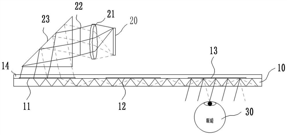
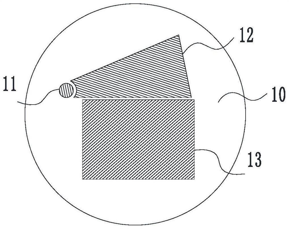
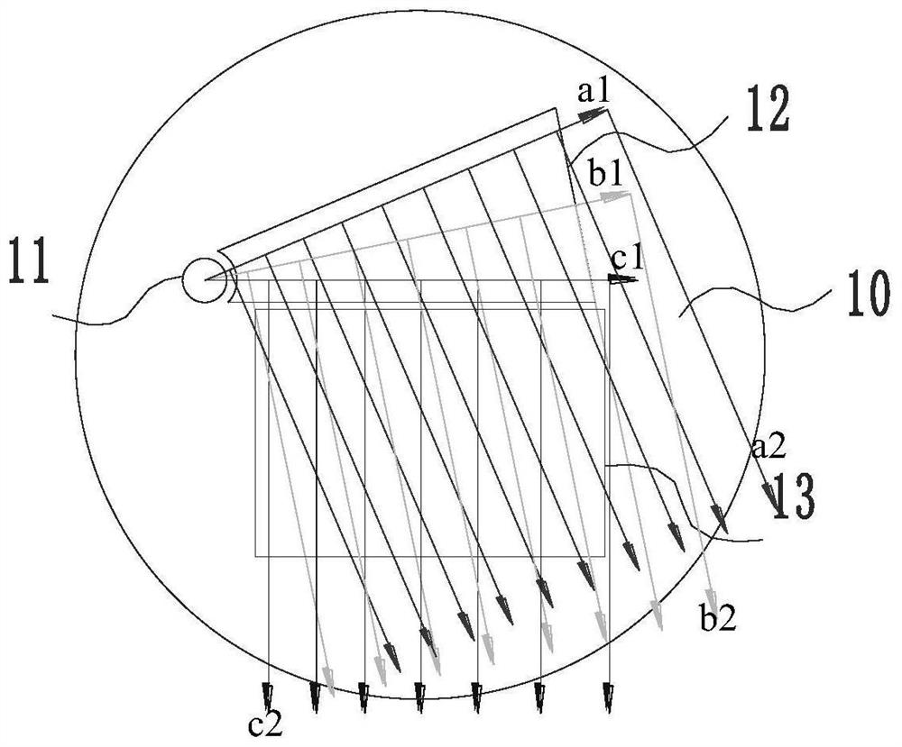
[0022] The present application will be further described below in combination with specific embodiments and accompanying drawings. It can be understood that the illustrative embodiments of the present disclosure include but are not limited to diffraction grating waveguides and AR display devices, and the specific embodiments described here are only for explaining the present application rather than limiting the present application. In addition, for the convenience of description, only some but not all structures or processes related to the present application are shown in the drawings.

[0023] The implementation of the present application will be described by specific specific examples below, and those skilled in the art can easily understand other advantages and effects of the present application from the content disclosed in this specification. Although the description of the present application will be introduced in conjunction with a preferred embodiment, it does not mean...


PUM

PropertyMeasurementUnit
depthaaaaaaaaaa

Abstract

The invention provides a diffraction grating waveguide and AR display equipment. The diffraction grating waveguide comprises a waveguide plate; when incident light enters the coupling-in grating, the direction of the incident light is changed, the incident light enters the waveguide plate, the incident light enters the turning grating after being totally reflected in the waveguide plate, the incident light enters the waveguide plate after the direction of the incident light is changed in the turning grating, and the incident light enters the waveguide plate after the direction of the incident light is changed in the turning grating. The light enters the coupling-out grating after being totally reflected in the waveguide plate, and is emitted after the direction of the light is changed in the coupling-out grating; wherein the relative phase angle rho of the coupling-in grating and the turning grating is equal to the relative phase angle rho of the turning grating and the coupling-out grating; the grating period of the coupling-in grating and the grating period of the coupling-out grating are d, and the grating period of the turning grating is d / 2 cos rho. According to the diffraction grating waveguide and the AR display device, the coupled-out light beam can reproduce information of the coupled-in light beam, distortion in light beam propagation is reduced, and a user can see a picture consistent with an image source.

Description

technical field [0001] The invention relates to the field of near-eye display optics, in particular to a diffraction grating waveguide and an AR display device. Background technique [0002] Near-eye display systems such as AR usually include core components such as image sources, beam collimating lens groups, and transmission waveguides. The image of the image source is usually displayed by a micro-display. The beam collimating lens group is used to convert the beams with different angle information emitted by the image point into parallel light. The transmission waveguide is used to transmit the image from the display screen to the human eye. , to modulate the collimated beam. Transmission waveguide elements may include lenses, mirrors, waveguide plates (tubes), holograms, and diffraction gratings, among others. [0003] Diffraction grating waveguide is a transmission waveguide that is currently valued by the industry and widely used, including in-coupling gratings, defl...

Claims


Application Information

Patent Timeline
Patent Type & Authority Applications(China)
IPC IPC(8): G02B6/00G02B5/18G02B27/00G02B27/01
Inventor 何新东王基亭吕强
Owner IRAY TECH CO LTD
Features
  • R&D
  • Intellectual Property
  • Life Sciences
  • Materials
  • Tech Scout
  • Unparalleled Data Quality
  • Higher Quality Content
  • 60% Fewer Hallucinations
Learn More