A battery management module of a storage battery and its method, device and storage medium

A battery management module and battery management technology, applied in the direction of battery circuit devices, circuit devices, measuring devices, etc., can solve the problem of affecting the service life of batteries, increasing the cost of smart grid operation and maintenance, the workload of operation and maintenance personnel, and affecting the stable operation of smart terminals, etc. problem, achieve the effect of improving work efficiency and simplifying management methods

Active Publication Date: 2022-07-08
GUANGDONG POWER GRID CO LTD DONGGUAN POWER SUPPLY BUREAU
View PDF5 Cites 0 Cited by
  • Summary
  • Abstract
  • Description
  • Claims
  • Application Information

AI Technical Summary

Problems solved by technology

However, the self-activation performance test and internal resistance test of the battery itself are not involved, and the test can only be performed after the battery is artificially removed from the smart grid.
Manual operation not only affects the stable operation of the smart terminal, but also affects the service life of the battery due to the continuous disassembly and assembly of the battery, which increases the operation and maintenance cost of the smart grid and the workload of the operation and maintenance personnel.

Method used


Image

  • A battery management module of a storage battery and its method, device and storage medium
  • A battery management module of a storage battery and its method, device and storage medium
  • A battery management module of a storage battery and its method, device and storage medium

Examples


Embodiment 1

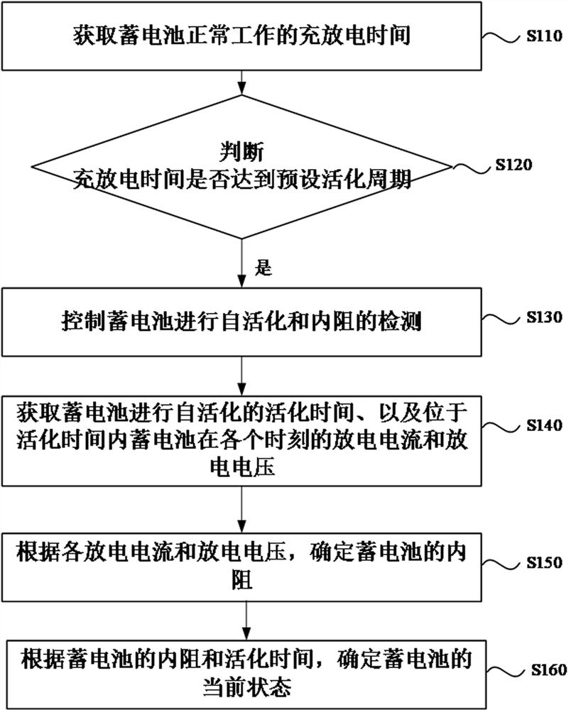
[0052] figure 1 It is a schematic flowchart of a battery management method for a storage battery according to Embodiment 1 of the present invention. The method may be executed by a battery management device for a storage battery, and the device may be composed of hardware and / or software. The battery management method of the storage battery provided by the embodiment of the present invention includes the following steps:

[0053] S110. Acquire the charging and discharging time of the battery in normal operation.

[0054]Among them, the battery can convert chemical energy into electrical energy during discharge, and the battery can store electrical energy as chemical energy during charging. The type of the battery may be a lead-acid battery or a lithium iron phosphate battery, and the type of the battery is not specifically limited here. The battery can be a single cell, or it can include one or more battery packs composed of multiple single cells. Here, the number and compos...

Embodiment 2

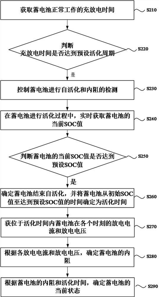
[0071] figure 2 This is a schematic flowchart of a battery management method for a storage battery according to the second embodiment of the present invention. On the basis of the above embodiment, a solution for determining the self-activation time of the storage battery is specifically provided. The technical solution of this embodiment includes:

[0072] S210 , acquiring the charging and discharging time of the battery in normal operation.

[0073] S220. Determine whether the charging and discharging time reaches the preset activation period, and if so, execute S230.

[0074] S230, control the battery to perform self-activation and internal resistance detection.

[0075] S240. During the activation process of the battery, obtain the current SOC value of the battery in real time.

[0076] S250: Determine whether the current SOC value of the battery reaches the preset SOC value, and if so, execute S260.

[0077] S260. Determine that the self-activation of the battery end...

Embodiment 3

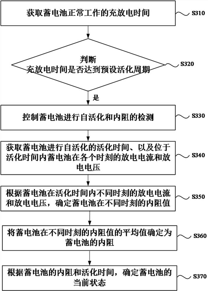
[0085] image 3 This is a schematic flowchart of a battery management method for a storage battery according to Embodiment 3 of the present invention. On the basis of the above embodiment, a solution for determining the self-activation time of the storage battery is specifically provided. The technical solution of this embodiment includes:

[0086] S310 , obtaining the charging and discharging time of the battery in normal operation.

[0087] S320. Determine whether the charging and discharging time reaches the preset activation period, and if so, execute S330.

[0088] S330, control the battery to perform self-activation and internal resistance detection.

[0089] S340 , acquiring the activation time during which the battery performs self-activation, and the discharge current and discharge voltage of the battery at various moments within the activation time.

[0090] S350. Determine the internal resistance of the battery at different times according to the discharge current ...


PUM


Abstract

The invention discloses a battery management module of a storage battery and a method, a device and a storage medium thereof. The method is applied to the battery management module of the storage battery, and includes: acquiring the charging and discharging time of the storage battery in normal operation; judging whether the charging and discharging time reaches a preset activation time cycle; if so, control the battery to perform self-activation and internal resistance detection; obtain the activation time of the battery for self-activation, as well as the discharge current and discharge voltage of the battery at each moment within the activation time; according to each discharge current and discharge voltage, determine Internal resistance of the battery; according to the internal resistance and activation time of the battery, determine the current state of the battery. The invention can control the battery to perform self-activation and internal resistance detection, avoids the influence of the operation of the smart grid due to manual detection, simplifies the battery management method, and improves the work efficiency of the smart grid operation and maintenance personnel.

Description

technical field [0001] The present invention relates to the field of battery intelligent management, in particular to a battery management module of a storage battery and a method, a device and a storage medium thereof. Background technique [0002] With the continuous development of smart grid, the investment in smart terminal equipment is increasing. Using smart terminals can effectively monitor the operation status of the entire smart grid. The battery is the main component that provides backup power for intelligent terminal equipment. [0003] In the prior art, the management and monitoring of the battery usually use a battery management module. The management module can set the required voltage, current range, charging and discharging time of the battery, and control the external power supply to supply power to the battery. However, the self-activation performance test and internal resistance test of the battery itself are not involved, and the test can only be perfor...

Claims


Application Information

Patent Timeline
Patent Type & Authority Patents(China)
IPC IPC(8): H01M10/42H02J7/00G01R31/388G01R31/389G01R31/396
CPCH01M10/4242H01M10/425H02J7/0048G01R31/388G01R31/389G01R31/396H01M2010/4271Y02E60/10
Inventor 黄庆铿梁永昌陈敬禧钱玉喜
Owner GUANGDONG POWER GRID CO LTD DONGGUAN POWER SUPPLY BUREAU
Why Eureka
Try Eureka