High-speed self-ventilation traction motor

A traction motor and self-ventilation technology, applied in cooling/ventilation devices, asynchronous induction motors, electromechanical devices, etc., can solve problems such as insufficient environmental adaptability, unreasonable motor shaft extension structure, and unsuitable high-speed self-ventilating motors.

Pending Publication Date: 2022-04-15
CRRC YONGJI ELECTRIC CO LTD
View PDF0 Cites 1 Cited by
  • Summary
  • Abstract
  • Description
  • Claims
  • Application Information

AI Technical Summary

Problems solved by technology

[0007] The present invention solves the problem of cleaning the dust filter screen of the existing self-ventilating traction motor, the problem that the typical ventilation structure is not suitable for high-speed self-ventilating motors, and the unreasonable shaft extension structure of the existing motor shaft leads to poor coupling fastness, coupling Due to the high failure rate of disassembly and assembly of shaft joints and the insufficient environmental adaptability of existing motors throughout their life cycle, a high-speed self-ventilated traction motor is provided

Method used


Image

  • High-speed self-ventilation traction motor
  • High-speed self-ventilation traction motor
  • High-speed self-ventilation traction motor

Examples


Embodiment Construction

[0039] The present invention will be further described below in conjunction with specific embodiments.

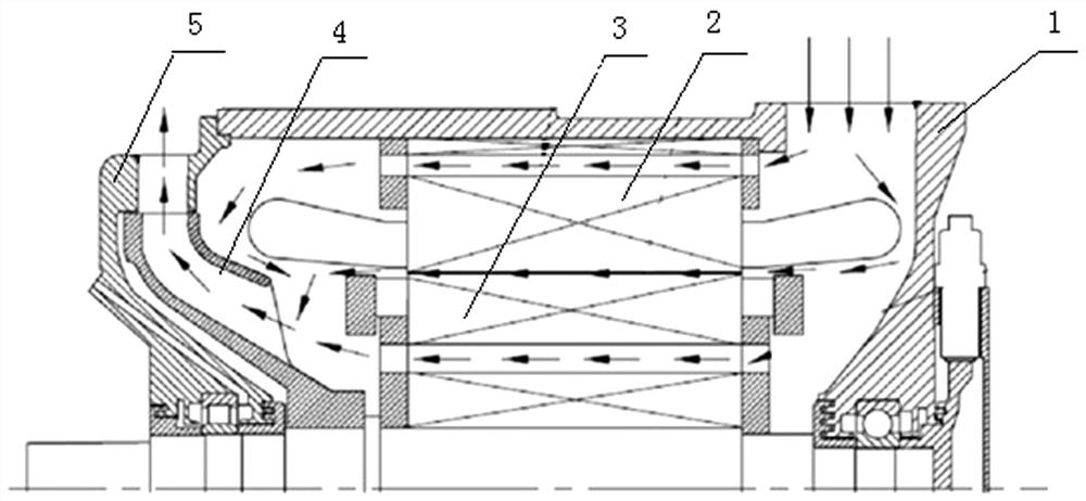
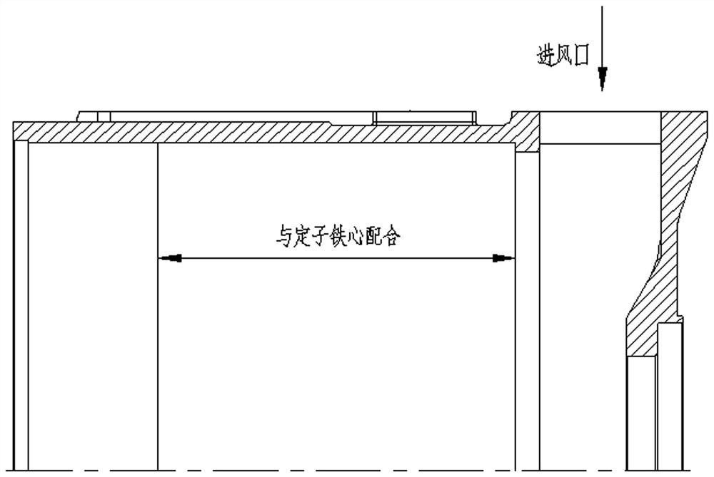
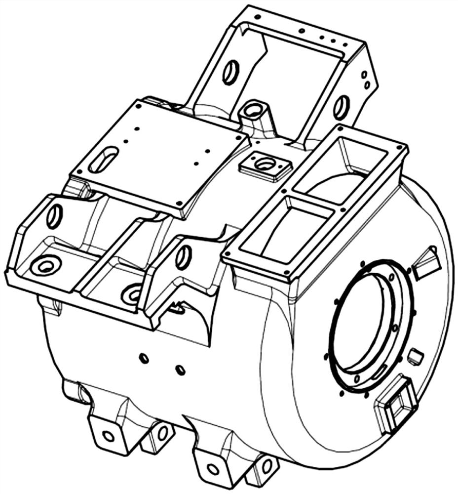
[0040] A high-speed self-ventilated traction motor such as Figure 2~Figure 24Shown: including stator assembly, rotor assembly 3, fan 4 and transmission end cover 5; the stator assembly includes frame 1, stator assembly 2, connecting wire 6, junction box 7 and sealant 8; the stator assembly 2 The heat sleeve is in the base 1, the top of the non-transmission end of the base 1 is provided with an air inlet, the transmission end of the base 1 is open, and the non-transmission end is an open structure; the stator assembly 2 includes a stator Iron core 2.4, coil 2.8, end hoop 2.9 and potting body 2.7, the transmission end of the stator iron core 2.4 is provided with a transmission end stator end plate 2.2 and a transmission end stator pressure plate 2.1, the transmission end stator pressure plate 2.1 is pressed against the transmission end stator Outside the end plate 2.2, the ...


PUM


Abstract

The invention discloses a high-speed self-ventilation traction motor, and relates to the field of traction motor heat dissipation. The interior of the traction motor is a U-shaped air path, and cooling air enters the motor from an air inlet in the top of a base and is divided into three paths, namely a stator air path, an air gap air path and a rotor air path. And the three paths of cooling air are converged and extracted through a fan arranged at the transmission end of the rotating shaft and are exhausted through air outlets formed in the circumferential direction of the side edge of the transmission end cover. According to the invention, the stator punching sheets of the shrinkage fit type stator are integrally tensioned with the buckle sheets by adopting the dovetail grooves at the back, and the buckle sheets are provided with wind paths, so that the weight and noise of the motor can be reduced. The novel shaft extension structure is adopted, the connection reliability of the coupling is improved, and the damage rate of repeated disassembly and assembly operation of the coupling to shaft extension is reduced. Encapsulation bodies are additionally arranged at notches at two ends of the coil, and sealing colloid is filled in a gap between a connecting line and a motor base outlet hole, so that the overall insulation performance of the stator is improved. And a paint-dipping special-shaped hard copper connecting wire is adopted, so that the fault of low insulation resistance of a wire connecting part is eliminated while the connecting strength is met.

Description

technical field [0001] The invention relates to the field of heat dissipation of traction motors, in particular to a high-speed self-ventilated traction motor. Background technique [0002] Due to the advantages of small weight and simple structure, self-ventilated motors have become the mainstream direction of traction motors for intercity and urban EMUs. As the OEMs require higher and higher maximum working speeds of motors, this puts forward more stringent requirements on the design performance of motor ventilation structures (especially noise and temperature rise) and the assembly reliability of couplings. At the same time, the environmental adaptability requires the traction motor to have sufficient resistance in the whole life cycle to resist the impact of dust, yellow sand, snow and rain. [0003] In the ventilation structure design of the existing self-ventilated traction motor, by opening ventilation holes in the yoke of the rotor core, the cooling air runs through...

Claims


Application Information

Patent Timeline
Patent Type & Authority Applications(China)
IPC IPC(8): H02K5/20H02K9/06H02K1/16H02K3/50H02K5/22H02K3/38H02K5/10H02K17/16
CPCH02K17/165H02K5/207H02K9/06H02K1/165H02K3/50H02K5/225H02K3/38H02K5/10
Inventor 李世杰李广赵宇坤张婷王津郭岚岚
Owner CRRC YONGJI ELECTRIC CO LTD
Why Eureka
Try Eureka