Device and method for detecting shield tunnel segment and wall back grouting effect

A technology of grouting behind the shield tunnel segment and wall, which is applied in the direction of measuring devices, tunnels, tunnel linings, etc., and can solve problems such as structural deformation, inability to guide grouting operations in real time and effectively, and damage

Active Publication Date: 2022-04-19
SHANDONG UNIV +1
View PDF11 Cites 1 Cited by
  • Summary
  • Abstract
  • Description
  • Claims
  • Application Information

AI Technical Summary

Problems solved by technology

[0002] Synchronous grouting in shield tunnels is an important measure to control ground deformation and protect existing tunnels, bridges and surrounding environments. However, the grouting form is not easy to control; Cause partial or overall dislocation, drift, structural deformation, cracking and other forms of damage to shield tunnel lining segments
[0003] The inventors of the present disclosure found that the shape and filling degree of the grouting body at the back of the segment cannot be effectively determined, so it is impossible to guide the grouting operation in real time and effectively

Method used


Image

  • Device and method for detecting shield tunnel segment and wall back grouting effect
  • Device and method for detecting shield tunnel segment and wall back grouting effect
  • Device and method for detecting shield tunnel segment and wall back grouting effect

Examples


Embodiment 1

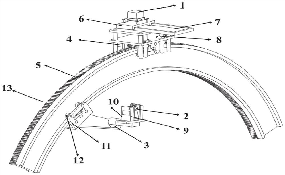
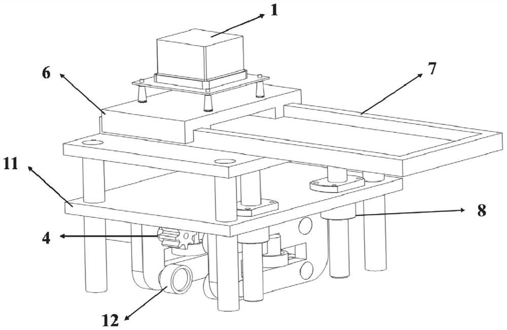
[0031] Such as figure 1 As shown, this embodiment provides a device for detecting grouting effect of shield tunnel segment and wall, including ring guide rail 5, geological radar device and laser scanner device;

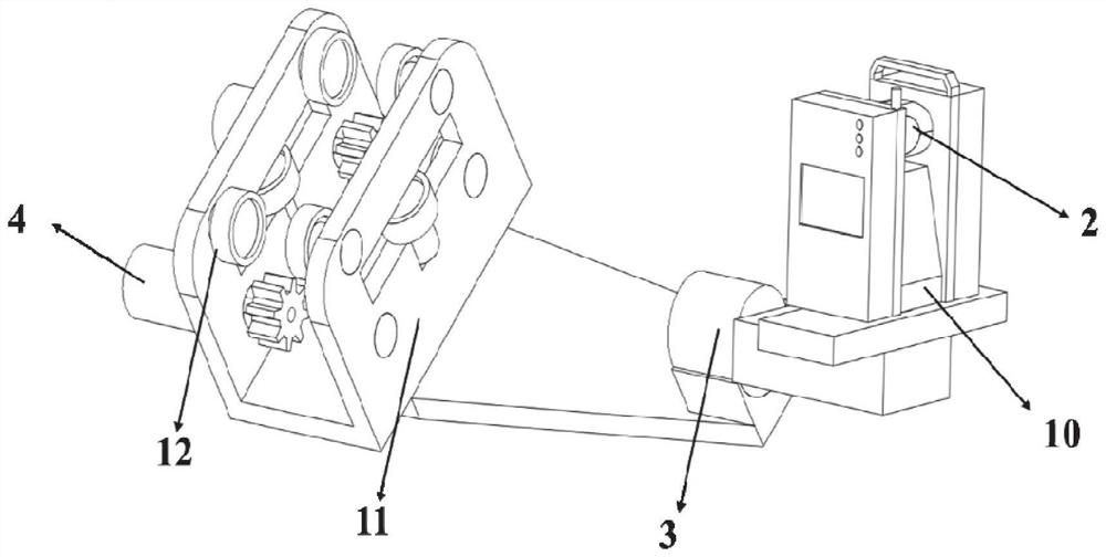
[0032] The geological radar device is slidably arranged on the outside of the circular guide rail 5, and the laser scanner device is slidably arranged on the inside of the circular guide rail 5; preferably, the circular guide rail 5 has a semicircular structure.

[0033] Specifically, through the movement of the geological radar device and the laser scanner device on the circular guide rail 5, the three-dimensional fusion analysis technology of the three-dimensional laser scanner and the geological radar data is studied, and the three-dimensional laser scanning and the geological radar are integrated. The shield tunnel segment-grouting body detection scheme builds a three-dimensional geological model of "segment-grouting body-surrounding rock mass", realizes rapid di...

Embodiment 2

[0043] This embodiment provides a method for detecting the grouting effect of the shield tunnel segment and the back wall, using the device for detecting the grouting effect of the shield tunnel segment and the back wall as described in the first aspect, include:

[0044] The ground radar performs its own height adjustment and longitudinal movement, and the laser scanner is always kept in the horizontal direction;

[0045] The ground radar and laser scanner move within the range of 0° to 180°. With the advancement of the shield, the ground radar and laser scanner realize visual inspection of the shield tunnel segment and grouting behind the wall along the ring direction.


PUM


Abstract

The invention discloses a device and a method for detecting a shield tunnel segment and a wall back grouting effect. The device comprises an annular guide rail, a geological radar device and a laser scanner device, the geological radar device is arranged on the outer side of the annular guide rail in a sliding mode, and the laser scanner device is arranged on the inner side of the annular guide rail in a sliding mode. A three-dimensional laser scanner and geological radar data three-dimensional fusion analysis technology is researched, a shield segment-grouting body detection scheme integrating three-dimensional laser scanning and geological radar is formed, a segment-grouting body-surrounding rock body three-dimensional geological model is constructed, segment health rapid diagnosis and grouting real-time sensing are achieved, and construction-grouting cooperative control is achieved.

Description

technical field [0001] The disclosure belongs to the field of post-wall grouting and segment detection during the construction period of a shield tunnel, and in particular relates to a device and method for detecting the effect of shield tunnel segment and post-wall grouting. Background technique [0002] Synchronous grouting in shield tunnels is an important measure to control ground deformation and protect existing tunnels, bridges and surrounding environments. However, the grouting form is not easy to control; Cause partial or overall dislocation, drift, structural deformation, cracking and other forms of damage to shield tunnel lining segments. [0003] The inventors of the present disclosure found that the shape and filling degree of the grouting body at the back of the segment cannot be effectively determined, so that the grouting operation cannot be guided effectively in real time. Contents of the invention [0004] In order to solve the above problems, the present...

Claims


Application Information

Patent Timeline
Patent Type & Authority Applications(China)
IPC IPC(8): E21D9/00E21D9/06F16M11/04F16M11/18F16M13/02G01S13/88G01N21/84E21D11/08E21D11/10
CPCE21D9/003E21D9/0609F16M11/043F16M11/046F16M11/045F16M11/18F16M13/02G01S13/885G01N21/84E21D11/08E21D11/105
Inventor 陈迪杨魏光宾江浩魏亮王旌王海波孙子正何敬源
Owner SHANDONG UNIV
Why Eureka
Try Eureka