Humidifier and fuel cell humidifying gas system

A humidifier and electric stack technology, which is applied in the direction of fuel cells, fuel cell additives, fuel cell heat exchange, etc., can solve the problems of high cost and low service life of fuel cell humidifiers

Pending Publication Date: 2022-04-19
国家电投集团氢能科技发展有限公司 +1
View PDF0 Cites 0 Cited by
  • Summary
  • Abstract
  • Description
  • Claims
  • Application Information

AI Technical Summary

Problems solved by technology

[0003] In related technologies, fuel cell humidifiers

Method used


Image

  • Humidifier and fuel cell humidifying gas system
  • Humidifier and fuel cell humidifying gas system
  • Humidifier and fuel cell humidifying gas system

Examples


Embodiment Construction

[0032] Embodiments of the invention are described in detail below, examples of which are illustrated in the accompanying drawings. The embodiments described below by referring to the figures are exemplary and are intended to explain the present invention and should not be construed as limiting the present invention.

[0033] A humidifier according to an embodiment of the present invention will be described below with reference to the drawings.

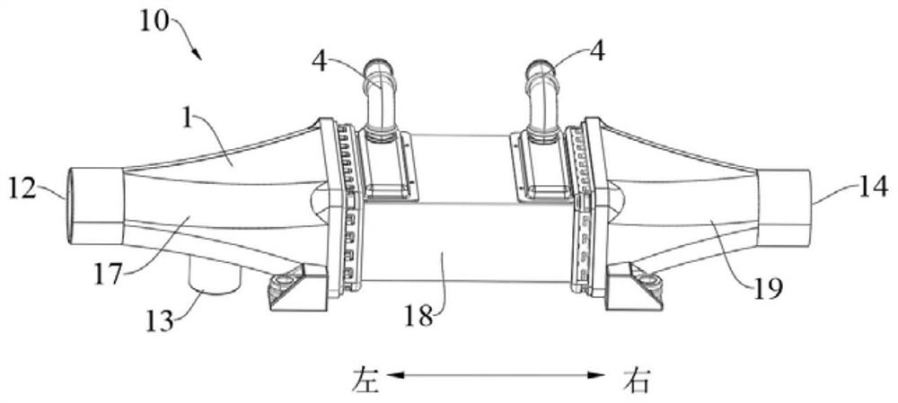
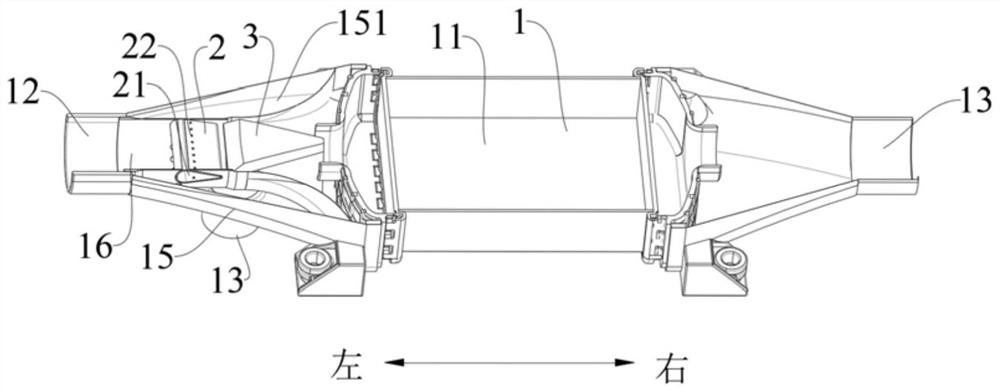
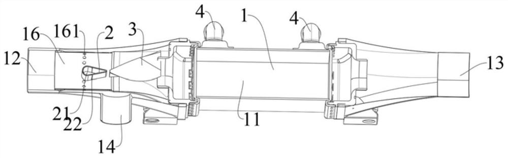
[0034] Such as Figure 1-5 As shown, the humidifier of the embodiment of the present invention includes a shell 1 , a core 2 and a spoiler 3 .

[0035] The housing 1 has a chamber 11, a first inlet 12, a second inlet 13 and an outlet 14, and the first inlet 12, the second inlet 13 and the outlet 14 are all communicated with the chamber 11, and the first inlet 12 and the outlet 14 are along the housing. 1 in the length direction (such as figure 1 The left and right directions shown) are oppositely arranged, and the second inlet 13 is...


PUM


Abstract

The invention discloses a humidifier and a fuel cell humidification system.The humidifier comprises a shell, a core and a spoiler, the shell is provided with a cavity, a first inlet, a second inlet and an outlet, and the first inlet, the second inlet and the outlet are all communicated with the cavity; the shell is provided with a first inlet and an outlet, the first inlet and the outlet are oppositely arranged along the length direction of the shell, the outlet is arranged adjacent to the first inlet, the core body is arranged in the cavity, the outer peripheral surface of the core body and the inner peripheral surface of the shell are arranged at an interval, the core body is arranged adjacent to the second inlet, and the core body is arranged in the cavity. The core body is arranged in the cavity, the cross section area of the core body is gradually increased in the direction towards the first inlet, and the spoiler is arranged in the cavity and arranged at the end, close to the outlet, of the core body. The humidifier has the advantages of being simple in structure, low in cost, good in humidifying effect and the like.

Description

technical field [0001] The invention relates to the field of manufacturing fuel cells, in particular to a humidifier and a fuel cell humidification system. Background technique [0002] During the electrochemical reaction of the fuel cell, the proton exchange membrane needs to maintain a certain humidity. The fuel cell humidification methods include bubbling humidification, enthalpy wheel humidification, spray humidification, and hollow fiber membrane tube humidification technology. [0003] In related technologies, fuel cell humidifiers are relatively expensive and have a short service life. Contents of the invention [0004] The present invention is based on the inventor's discovery and recognition of the following facts and problems: [0005] In the related art, the fuel cell humidification system, such as figure 1 As shown, the air is filtered in the air filter, compressed in the air compressor, cooled in the intercooler, humidified in the tube side of the hollow fib...

Claims


Application Information

Patent Timeline
IPC IPC(8): H01M8/04119H01M8/04007
CPCH01M8/04126H01M8/04074Y02E60/50
Inventor 王雪娥陈璐苏前跃常天文
Owner 国家电投集团氢能科技发展有限公司
Why Eureka
Try Eureka