Supercharge Your Innovation With Domain-Expert AI Agents!

Spraying type medical equipment disinfection cabinet

A technology for medical equipment and sterilization cabinets, applied in the field of sterilization cabinets, can solve problems such as poor disinfection methods and inability to ensure complete disinfection of equipment, and achieve good disinfection effects, prevent mildew, and improve work efficiency.

Pending Publication Date: 2022-04-22
钟德成
View PDF8 Cites 0 Cited by
  • Summary
  • Abstract
  • Description
  • Claims
  • Application Information

AI Technical Summary

Problems solved by technology

[0005] In order to overcome the disadvantages that the disinfection effect of the existing medical equipment disinfection box that can be highly sterilized is relatively poor, and the equipment cannot be fully sterilized, the purpose of the present invention is to provide a sprayable medical equipment disinfection that can completely disinfect the equipment and form an assembly line cabinet

Method used


Image

  • Spraying type medical equipment disinfection cabinet
  • Spraying type medical equipment disinfection cabinet
  • Spraying type medical equipment disinfection cabinet

Examples


Embodiment 1

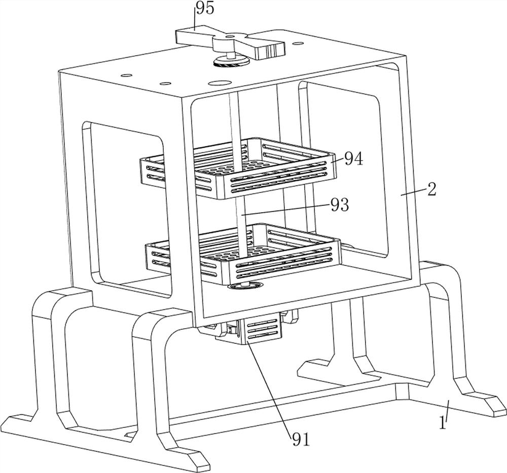
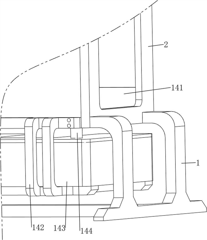
[0036] A sprayable medical equipment disinfection cabinet, such as Figure 1-6 Shown, comprising a support frame 1, housing 2, housing 3, first fixing block 4, first connecting rod 5, clamshell 6, second fixing block 7, limit rod 8, rotating mechanism 9 and spray mechanism 10, the upper side of the support frame 1 is bolted to the housing 2, housing 2 is provided with a bearing seat in the middle of the bottom of the housing 3, housing 2 the right front side of the upper and lower sides are equipped with a first fixing block 4, the first connecting rod 5 is connected between the two first fixing blocks 4, the first connecting rod 5 is provided with a clamshell to prevent the splash of disinfectant water 6, Housing 2 is provided with a second fixing block 7 on the left front side, the left side of the flap 6 is connected by means of a thread connection to the limit rod 8 for fixing the role, the limit rod 8 is coordinated with the second fixing block 7 threaded, the middle of the sh...

Embodiment 2

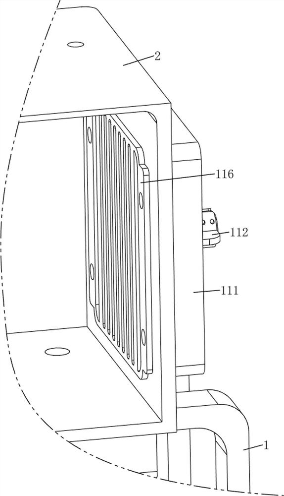
[0041] On the basis of Example 1, e.g., Figure 1 、 Figure 7 、 Figure 8 、 Figure 9 、 Figure 10 、 Figure 11 、 Figure 12 and Figure 13 Shown, further comprising a drying mechanism 11, the drying mechanism 11 includes a fixed shell 111, a fixed ring 112, a second motor 113, a fan 114, a heating wire 115 and a protective plate 116, the housing 2 on both sides of the wall are equipped with a fixed shell 111, the two fixed shells 111 are symmetrically provided with a fixed ring 112, between the two fixed rings on the left and right sides 112 are installed for the second motor 113, two second motor 113 output shafts are equipped with a fan that can blow out the air 114, Both fixing shells 111 are equipped with five heating wires 115 that can heat the equipment to dry, the housing 2 is equipped with a protective plate 116 on both sides of the interior wall, and the two fans 114 are located inside the fixed housing 111 on the same side.

[0042] When disinfecting the equipment, when the p...


PUM


Abstract

The invention relates to a disinfection cabinet, in particular to a medical equipment disinfection cabinet capable of spraying. The invention provides a sprayable medical equipment disinfection cabinet which is thorough in equipment disinfection and forms an assembly line type. A spraying type medical equipment disinfection cabinet comprises a supporting frame, a shell, a bearing seat, first fixing blocks, a first connecting rod and a turning cover, the shell is arranged on the upper side of the supporting frame, the bearing seat is arranged in the middle of the bottom of the shell, the first fixing blocks are arranged on the upper side and the lower side of the front side of the right portion of the shell, and the first connecting rod is connected between the two first fixing blocks. And a turning cover is rotationally arranged on the first connecting rod. The first motor works to drive the rotating rod and the protruding block to rotate, the protruding block makes intermittent contact with the inclined face of the rack, then disinfectant fluid is intermittently sprayed out of the spraying pipe to disinfect equipment, the spraying type operation can achieve the good disinfection effect, automatic operation is achieved, and manual disinfection is not needed.

Description

Technical field [0001] The present invention relates to a disinfection cabinet, in particular to a sprayable medical equipment disinfection cabinet. Background [0002] In medical diagnosis, a variety of conventional medical devices need to be disinfected after use, the use of conventional medical devices is very large, the disinfection of medical devices is also a very heavy work, conventional disinfection methods, will be unified into the disinfection bucket, whether it is the first addition of disinfectant water or after the way of adding disinfectant water, in the operation process, are prone to the risk of disinfectant spilled out of the barrel, easy to pollute medical personnel or the external environment, while directly soaking in the way of disinfection, disinfection time is longer, disinfection efficiency is low. [0003] Patent application no. CN201811057219.X a kind of medical equipment disinfection box can be efficiently sterilized, comprising a load plate, the top o...

Claims


Application Information

Patent Timeline
Patent Type & Authority Applications(China)
IPC IPC(8): A61L2/18A61L2/06A61L2/26F26B21/00
CPCA61L2/18A61L2/06A61L2/26F26B21/001
Inventor 钟德成
Owner 钟德成
Features
  • R&D
  • Intellectual Property
  • Life Sciences
  • Materials
  • Tech Scout
  • Unparalleled Data Quality
  • Higher Quality Content
  • 60% Fewer Hallucinations
Learn More