
Vapor chamber and heat dissipation device

A technology of soaking plate and heat dissipation cavity, which is applied in indirect heat exchangers, lighting and heating equipment, electrical components, etc., can solve the problem that the capillary force of capillary channels and the water storage capacity cannot be balanced, reduce the channel width, and reduce the channel water storage capacity. And other issues

Pending Publication Date: 2022-04-22
江西新菲新材料有限公司
View PDF0 Cites 0 Cited by
  • Summary
  • Abstract
  • Description
  • Claims
  • Application Information

AI Technical Summary

Problems solved by technology

[0003] At present, the capillary core of the vapor chamber is mainly composed of sintered porous inner wall, copper mesh or a composite of porous inner wall and copper mesh. In the process of realizing this application, the inventor found that there are at least the following problems in the prior art: Existing capillary pipes have a contradiction between capillary force and water storage capacity. In order to increase the capillary force of capillary pipes, it is necessary to reduce the size of the channel channel (effective meniscus radius), while reducing the width of the channel cannot obtain better The large depth will eventually greatly reduce the water storage capacity of the channel type

Method used


Image

  • Vapor chamber and heat dissipation device
  • Vapor chamber and heat dissipation device
  • Vapor chamber and heat dissipation device

Examples


Embodiment Construction

[0052] Embodiments of the present invention are described in detail below, examples of which are shown in the drawings, wherein the same or similar reference numerals denote the same or similar elements or elements having the same or similar functions throughout. The embodiments described below by referring to the figures are exemplary only for explaining the present invention and should not be construed as limiting the present invention.

[0053] In describing the present invention, it should be understood that the terms "center", "longitudinal", "transverse", "length", "width", "thickness", "upper", "lower", "front", " Orientation or position indicated by "back", "left", "right", "vertical", "horizontal", "top", "bottom", "inside", "outside", "clockwise", "counterclockwise", etc. The relationship is based on the orientation or positional relationship shown in the drawings, and is only for the convenience of describing the present invention and simplifying the description, ra...


PUM


Abstract

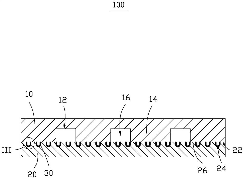
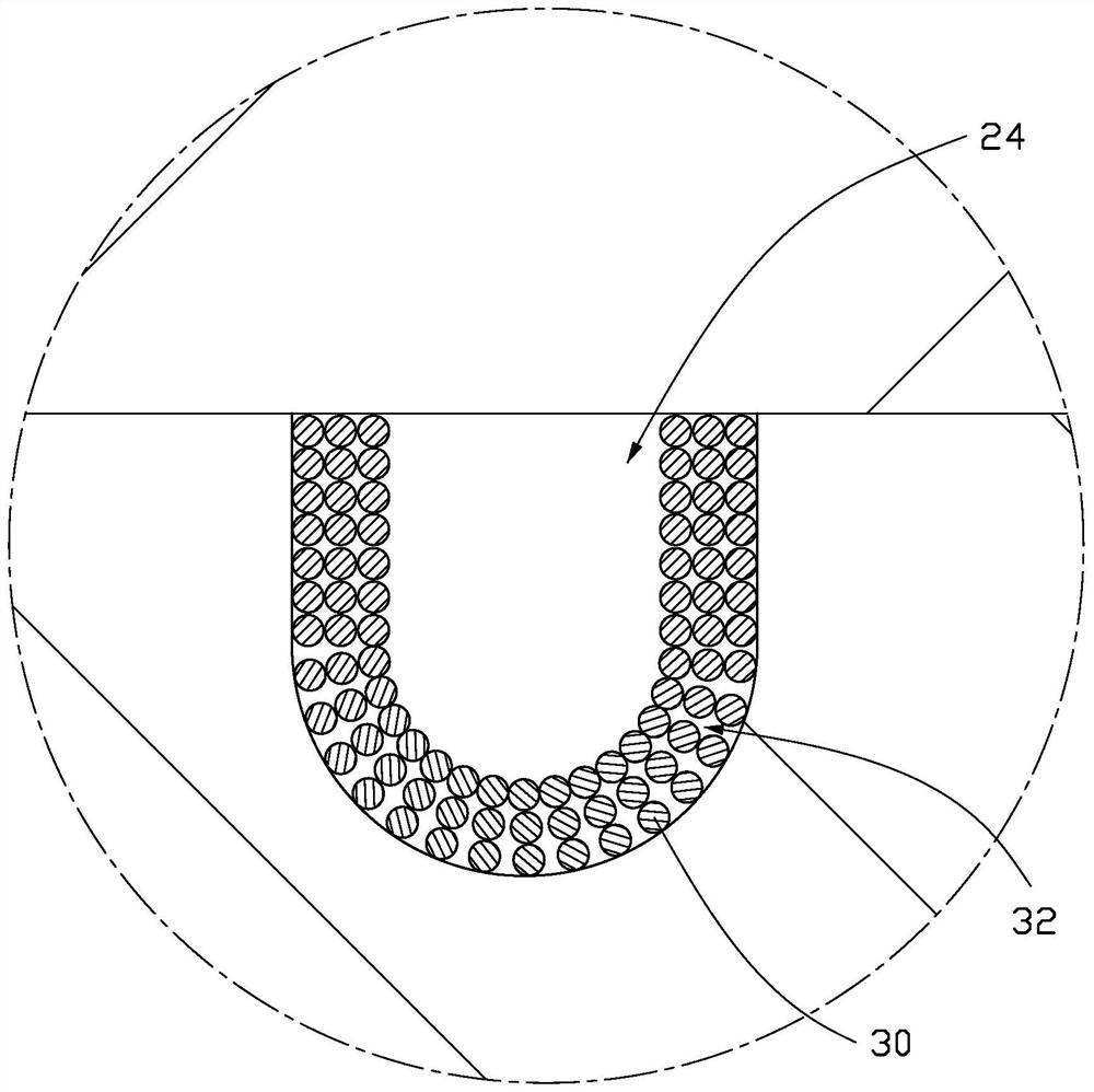
The invention discloses a vapor chamber and a heat dissipation device. The vapor chamber comprises a first cover plate which is provided with a first side, a plurality of supporting parts are arranged on the first side at intervals, and gaps among the supporting parts are communicated with one another and form a heat dissipation cavity; the second cover plate is provided with a second side, the second side is arranged opposite to the first side, the edge of the second side is connected with the edge of the first side in a sealed mode, a plurality of capillary grooves are formed in the second side, a plurality of hydrophilic nano-particles are stacked in the groove wall of each capillary groove, and gaps among the nano-particles are communicated; the end, close to the second cover plate, of the supporting part abuts against the groove walls of the capillary grooves, and each capillary groove communicates with the heat dissipation cavity. According to the vapor chamber, on the premise that the water storage capacity of the capillary grooves is not greatly changed, the overall capillary pressure of the capillary channels can be improved through the nanoparticles accumulated on the surfaces of the groove walls of the capillary grooves, and the heat dissipation effect is good.

Description

technical field [0001] The invention relates to the field of heat dissipation, in particular to a vapor chamber and a heat dissipation device. Background technique [0002] With the advent of the 5G communication era, the information processing capacity of mobile phone chips is increasing, and the power consumption and heat generation are also increasing, which puts higher requirements on the cooling system of mobile phones. Ultra-thin Vapor Chamber (VC), with its excellent heat dissipation effect and ultra-thin structure, is gradually becoming the standard configuration of 5G mobile phone cooling systems. Vapor chamber is a vacuum cavity with a fine structure on the inner wall. When the heat is transferred from the heat source to the heating end, the liquid working medium in the vacuum cavity starts to vaporize when heated, and the vaporized liquid working medium fills the entire vacuum cavity. When the vaporized liquid working medium reaches the condensation end, it will ...

Claims


Application Information

Patent Timeline
Patent Type & Authority Applications(China)
IPC IPC(8): F28D15/04H01L23/427H01L23/367H01L23/373B82Y30/00
CPCF28D15/046H01L23/427H01L23/3672H01L23/3733B82Y30/00
Inventor 孟锴钭忠尚高菁
Owner 江西新菲新材料有限公司
Learn More