Composite liquid absorption core and manufacturing method and application thereof

A manufacturing method and liquid-absorbing core technology, applied in lighting and heating equipment, indirect heat exchangers, etc., can solve the problems of uniform and continuous arrangement of difficult fibers, increase of local flow resistance, and increase of processing costs, so as to reduce sintering temperature and heat preservation Time, reduce flow resistance, increase the effect of capillary pressure

Pending Publication Date: 2022-01-28
GUANGDONG UNIV OF TECH
View PDF0 Cites 0 Cited by
  • Summary
  • Abstract
  • Description
  • Claims
  • Application Information

AI Technical Summary

Problems solved by technology

[0005] The above method still has the problems of large flow resistance, complicated process and high cost.
For example, it is difficult to achieve a uniform and continuous arrangement of fibers through the composite of copper powder and fiber, which may cause an increase in local flow resistance; the preparation of a liquid-absorbing core composited with grooves and sintered structures generally requires high-temperature sintering and secondary processing of the grooves and other different processes, greatly increasing the processing cost

Method used


Image

  • Composite liquid absorption core and manufacturing method and application thereof
  • Composite liquid absorption core and manufacturing method and application thereof
  • Composite liquid absorption core and manufacturing method and application thereof

Examples


Embodiment 1

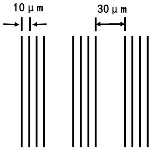
[0045] The size is 70×70×1mm 3 The surface of the copper plate is scanned by a short-pulse laser in the air, and the scanning area size is 68×68mm 2 , the laser and scanning parameters are: laser pulse width at half maximum 290fs, wavelength 515nm, repetition frequency 200kHz, laser energy flux density reaching the surface of the workpiece 2J / cm 2 , continuous parallel scanning. The scanning line pattern is a periodic array of parallel lines, figure 1 Shown is a schematic of an array of three parallel lines with a spacing of 10 μm between parallel lines and a spacing of 30 μm between arrays. The scanning speed is 10mm / s, and the number of scanning is 1 time. A unidirectional airflow field is applied during scanning. The unidirectional airflow field is formed by a high-speed micro-fan placed near the sample. The angle between the airflow direction and the sample surface and the laser scanning direction is controlled by controlling the relative position of the fan and the sa...

Embodiment 2

[0049] The size is 40×50×1mm 3 The C5191 phosphor copper plate, the surface is scanned by short pulse laser in the air, the scanning area size is 38×48mm 2 , the laser and scanning parameters are: laser pulse width at half maximum 10ps, wavelength 1030nm, repetition frequency 400kHz, laser energy flux density reaching the surface of the workpiece 1.5J / cm 2 , continuous parallel scanning, the scanning line spacing is 30 μm, the scanning speed is 40 mm / s, and the scanning is repeated 10 times. A unidirectional airflow field is applied during scanning. The one-way airflow field is realized by placing a vacuum tube near the sample. The vacuum tube is connected to a vacuum cleaner with a filter. By controlling the relative position of the vacuum tube and the sample, the clamping direction of the airflow direction, the sample surface and the laser scanning direction is controlled. Angle, the flow rate of the air flow is controlled by the power of the vacuum cleaner. In this examp...


PUM

PropertyMeasurementUnit
thicknessaaaaaaaaaa
diameteraaaaaaaaaa
widthaaaaaaaaaa

Abstract

The invention discloses a composite liquid absorption core and a manufacturing method and application thereof. The composite liquid absorption core comprises a groove and a nano-porous layer, and the nano-porous layer covers the surface of the inner wall of the groove. The composite liquid absorption core is provided with the groove structure and the nano-porous layer, the nano-porous layer can effectively increase capillary pressure, and the groove structure can effectively reduce flow resistance; and meanwhile, the evaporation and condensation processes of the working medium in the nano-porous layer are increased, so that the thermal resistance of the heat pipe and the vapor chamber device is effectively reduced.

Description

technical field [0001] The invention relates to the field of heat dissipation devices, in particular to a composite liquid-absorbing core and its manufacturing method and application. Background technique [0002] Both heat pipes and vapor chambers are heat transfer elements that use the phase change process of the medium to achieve rapid heat transfer. Among them, the heat pipe is a one-dimensional heat transfer device, which is generally tubular or flat. The liquid working medium is heated and evaporated at the evaporation end of the heat pipe, and the heat is taken away. The heat is the latent heat of evaporation of the working medium. It flows to the condensation section of the heat pipe, condenses into a liquid, and releases latent heat at the same time. Under the action of capillary force, the liquid flows back to the evaporation section. The vapor chamber is a two-dimensional heat transfer planar device, generally a flat plate structure with a large area. The workin...

Claims


Application Information

Patent Timeline
Patent Type & Authority Applications(China)
IPC IPC(8): F28D15/04
CPCF28D15/046
Inventor 龙江游李艳吴峻炜欧阳紫晴席明杰
Owner GUANGDONG UNIV OF TECH
Why Eureka
Try Eureka