Data collection device for switch cabinet sensor

A technology of data collection and switchgear, which is applied in the direction of measuring devices, instruments, measuring electricity, etc., can solve the problems of general detection accuracy, inability to obtain accurate data, and inability to know the data value of power distribution cabinets, etc., to achieve the goal of improving accuracy Effect

Pending Publication Date: 2022-04-22
FUXIN POWER SUPPLY COMPANY STATE GRID LIAONING ELECTRIC POWER +1
View PDF0 Cites 0 Cited by
  • Summary
  • Abstract
  • Description
  • Claims
  • Application Information

AI Technical Summary

Problems solved by technology

[0003] At present, the data collection method of switchgear in the prior art is fixed-point, so it is impossible to know the data value of each position inside the power distribution cabinet. Long-term data detection and collection at a certain place cannot obtain accurate data, which makes the detection accuracy In general, for this purpose, we propose a data collection device for switchgear sensors

Method used


Image

  • Data collection device for switch cabinet sensor
  • Data collection device for switch cabinet sensor
  • Data collection device for switch cabinet sensor

Examples


Embodiment 1

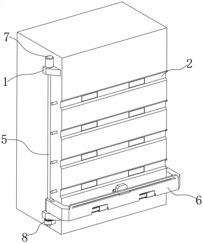
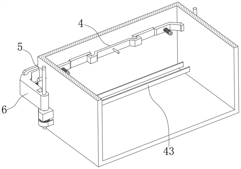
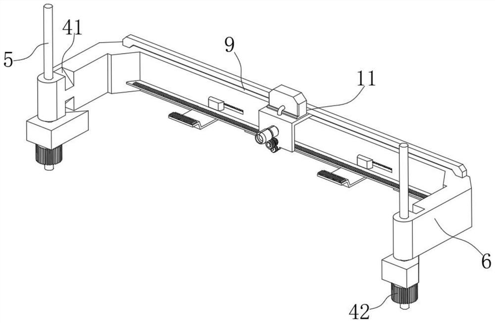
[0027] see figure 1 , figure 2 with Figure 9 , a data collection device for switchgear sensors in the figure, including fixed blocks 1 fixed on the top and bottom of both sides of the switchgear, and a plurality of grooves 2 are opened on the back side of the switchgear. There are two detection ports 3, and a closure 4 is installed at the position corresponding to the detection port 3 inside the switch cabinet, and an adjustment screw 5 is inserted between the two fixed blocks 1 on the same side, and the two adjustment screw rods 5 The outer thread is sleeved with a U-shaped plate 6, the drive motor 7 is fixed on the outside of the switch cabinet, and the output end of the drive motor 7 is fixed to the outer end of one of the adjusting screw rods 5, and the bottom of the two adjusting screw rods 5 is fixed with a linkage 8, The U-shaped plate 6 is provided with a moving port 9, and an L-shaped mobile station 10 is slidably inserted into the mobile port 9, and a data collec...

Embodiment 2

[0041] see Figure 4 with Figure 8 , this embodiment is further described for Example 1. The U-shaped plate 6 in the illustration is provided with an adjustment port 28 at the position corresponding to the detection port 3. A slide bar 29 is fixed inside the adjustment port 28, and the outside of the slide bar 29 is slidingly sleeved with Adjusting platform 30, the outer side of slide bar 29 is covered with extrusion spring 44 to push adjusting platform 30, and the outer end of adjusting platform 30 is fixed with L-shaped support platform 31, and the outer end of L-shaped support platform 31 is fixed with second tooth plate 32. One end of the rod 19 is fixed with a half gear 33 meshing with the second gear plate 32 , and the other end is fixed with a contact ball 34 that matches the adjustment platform 30 , and the outside of the transmission rod 19 is covered with a return spring for pushing the transmission gear 21 45.

[0042] It is worth noting that: in order to improve...

Embodiment 3

[0045] see image 3 with Figure 9 , this embodiment is further described for other embodiments. The closure member 4 in the illustration includes a sealing plate 36 inserted in the two detection ports 3, a connecting plate is fixed between the two sealing plates 36, and the two sealing plates 36 The outer sides are fixed with adjustable slant plates 37, and both the adjustable slant plates 37 and the connecting plates are slidingly inserted with limit pins 38 fixed to the inner wall of the switch cabinet, and the outer sides of the limit pins 38 at both ends are covered with return springs 39. Both ends are plugged with adjusting rods 40 that are in contact with the slope of the adjusting slant plate 37 , and there are adjusting grooves 41 at the positions corresponding to the adjusting rods 40 on both sides of the U-shaped plate 6 .

[0046] It should be noted that: every time the U-shaped plate 6 moves at the position corresponding to the groove 2, the adjustment rod 40 wi...


PUM


Abstract

The invention discloses a data collection device for a switch cabinet sensor, relates to the technical field of data detection and collection, solves the problem of inaccurate data collection during fixed-point detection, and comprises fixed blocks fixed at the top and the bottom of two sides of a switch cabinet, and sealing parts are installed at the positions, corresponding to detection ports, of the inner side of the switch cabinet. An adjusting screw rod is rotatably inserted between the two fixing blocks on the same side, the outer sides of the two adjusting screw rods are sleeved with a U-shaped plate in a threaded mode, a driving motor is fixed to the outer side of the switch cabinet, the output end of the driving motor is fixed to the outer end of one adjusting screw rod, linkage pieces are fixed to the bottoms of the two adjusting screw rods, and a moving opening is formed in the U-shaped plate; according to the invention, the U-shaped plate moving on the adjusting screw rod is designed, and the data collection mechanism is designed in the U-shaped plate, so that the temperature detection of all parts in the switch cabinet is satisfied, and the accuracy of the detection data is improved.

Description

technical field [0001] The invention relates to the technical field of data detection and collection, in particular to a data collection device for switchgear sensors. Background technique [0002] The power switchgear is an important equipment responsible for load distribution in the power system. Due to the large load current, some switchgears can pass through a current of up to 4000A for a long time, while the contact position of the contacts (plugs) in the cabinet is offset, the dynamic and static contact springs are loose, and the material Bad and other factors will lead to poor contact of the contacts, resulting in severe heat. According to the relevant requirements of the national standard GB763-1990 "Heating of AC high-voltage electrical appliances during long-term work", the maximum allowable temperature of bare copper or bare copper alloy contacts in a 10kV switch cabinet is 75°C, and the maximum temperature of the equipment joints in the cabinet must not exceed T...

Claims


Application Information

Patent Timeline
Patent Type & Authority Applications(China)
IPC IPC(8): G01R31/00
CPCG01R31/00
Inventor 于浩石鑫刘嘉欣王刚孙凤强莫中岳
Owner FUXIN POWER SUPPLY COMPANY STATE GRID LIAONING ELECTRIC POWER
Why Eureka
Try Eureka